Mode locking mechanism of electric plastic injection machine

An injection molding machine and mold clamping technology, which is applied in the field of mold clamping mechanisms of electric injection molding machines, can solve the problems of insufficient mold protection level, large deformation of the middle template, and high lubrication requirements, and achieve compact structure, uniform force, and easy disassembly and assembly. convenient effect

Active Publication Date: 2010-11-03
NINGBO HAIXING MACHINERY MFG
View PDF3 Cites 0 Cited by
  • Summary
  • Abstract
  • Description
  • Claims
  • Application Information

AI Technical Summary

Problems solved by technology

This structure inevitably has hinge points that are easy to wear, heavy structure, high lubrication requirements and serious pollution, large deformation of the middle template, and most importantly, the protection level of the mold is not high enough. If you are not careful, it may be as high as hundreds of thousands Even millions of defects such as mold damage

Method used


Image

  • Mode locking mechanism of electric plastic injection machine
  • Mode locking mechanism of electric plastic injection machine
  • Mode locking mechanism of electric plastic injection machine

Examples


Embodiment Construction

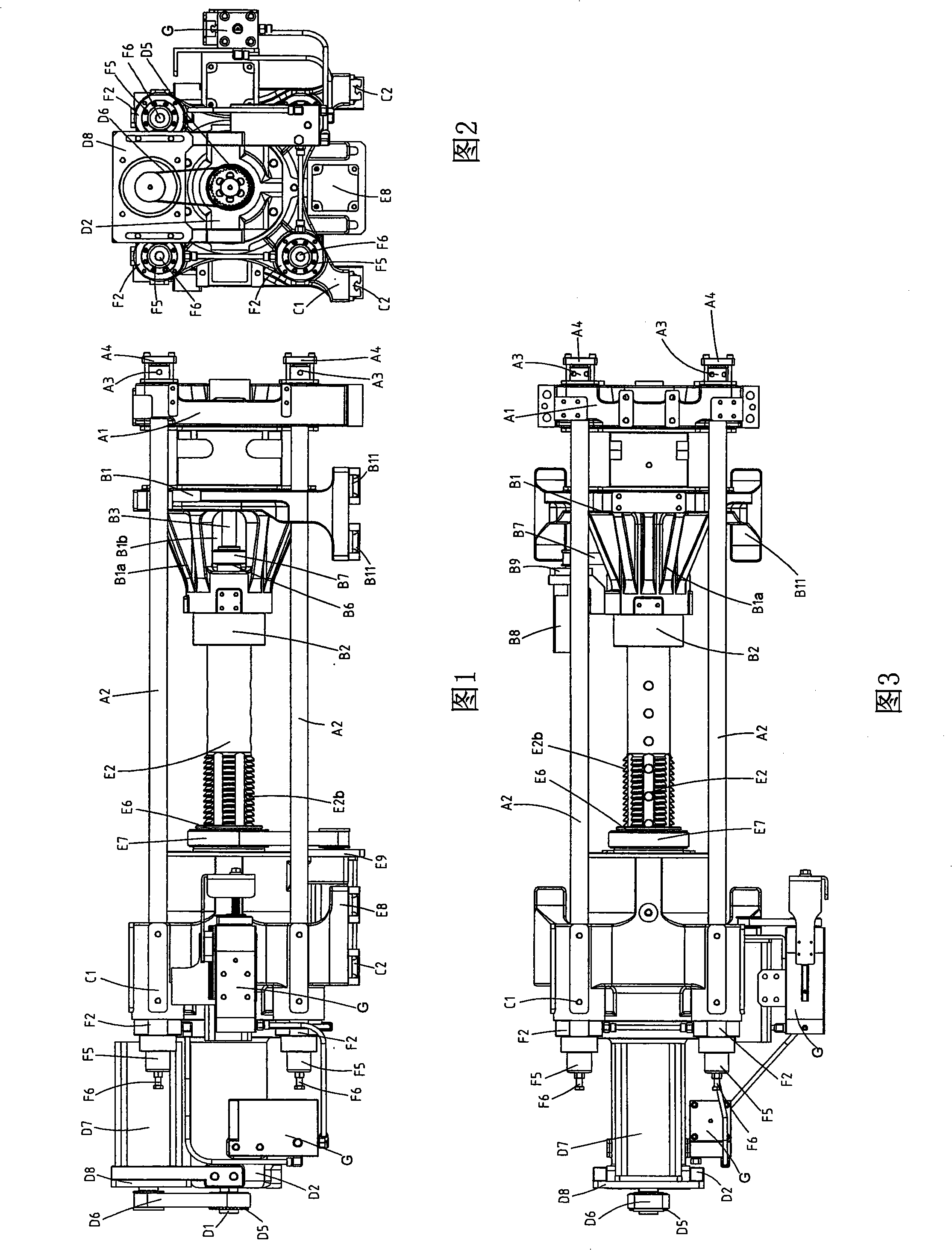
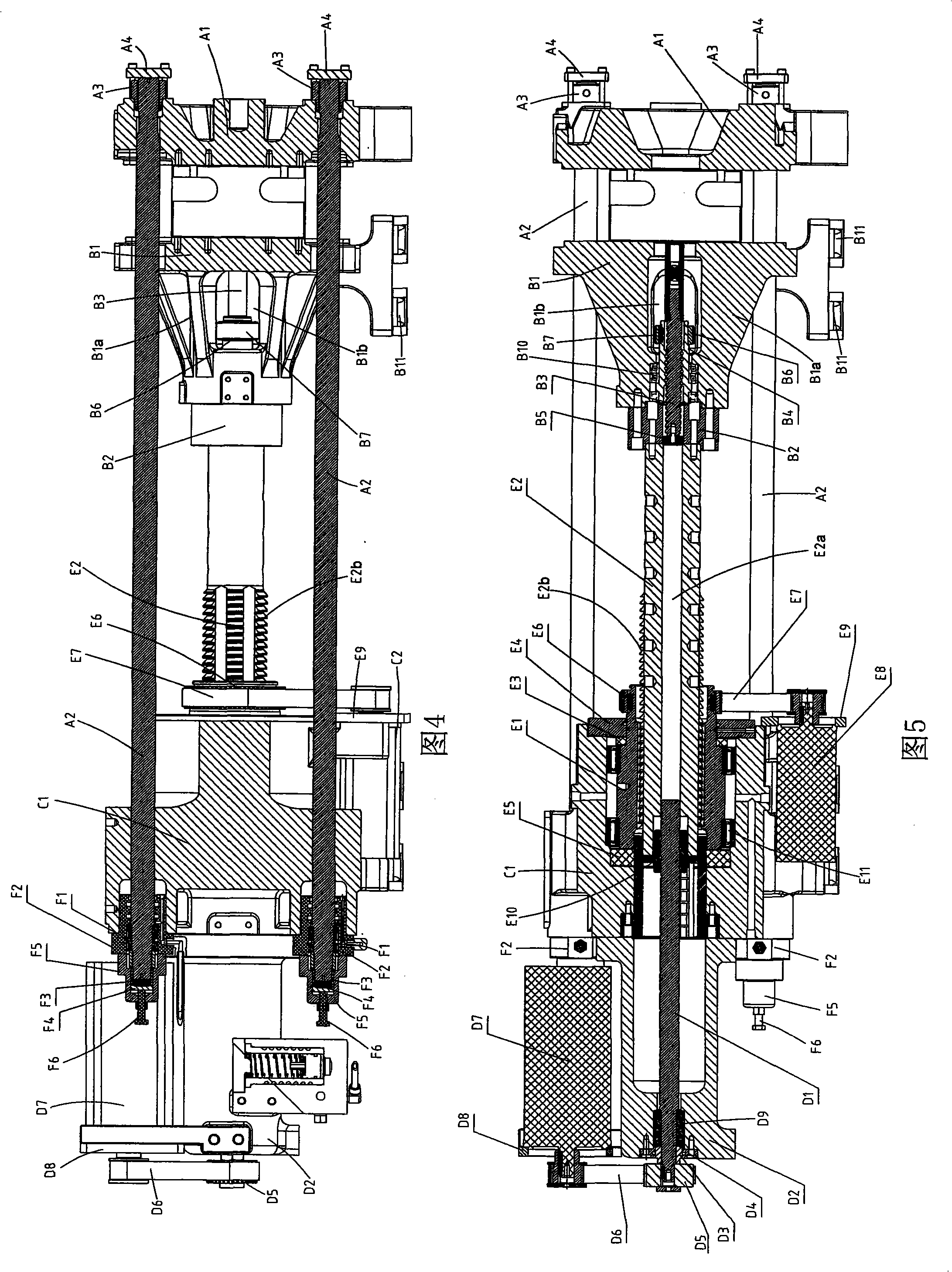
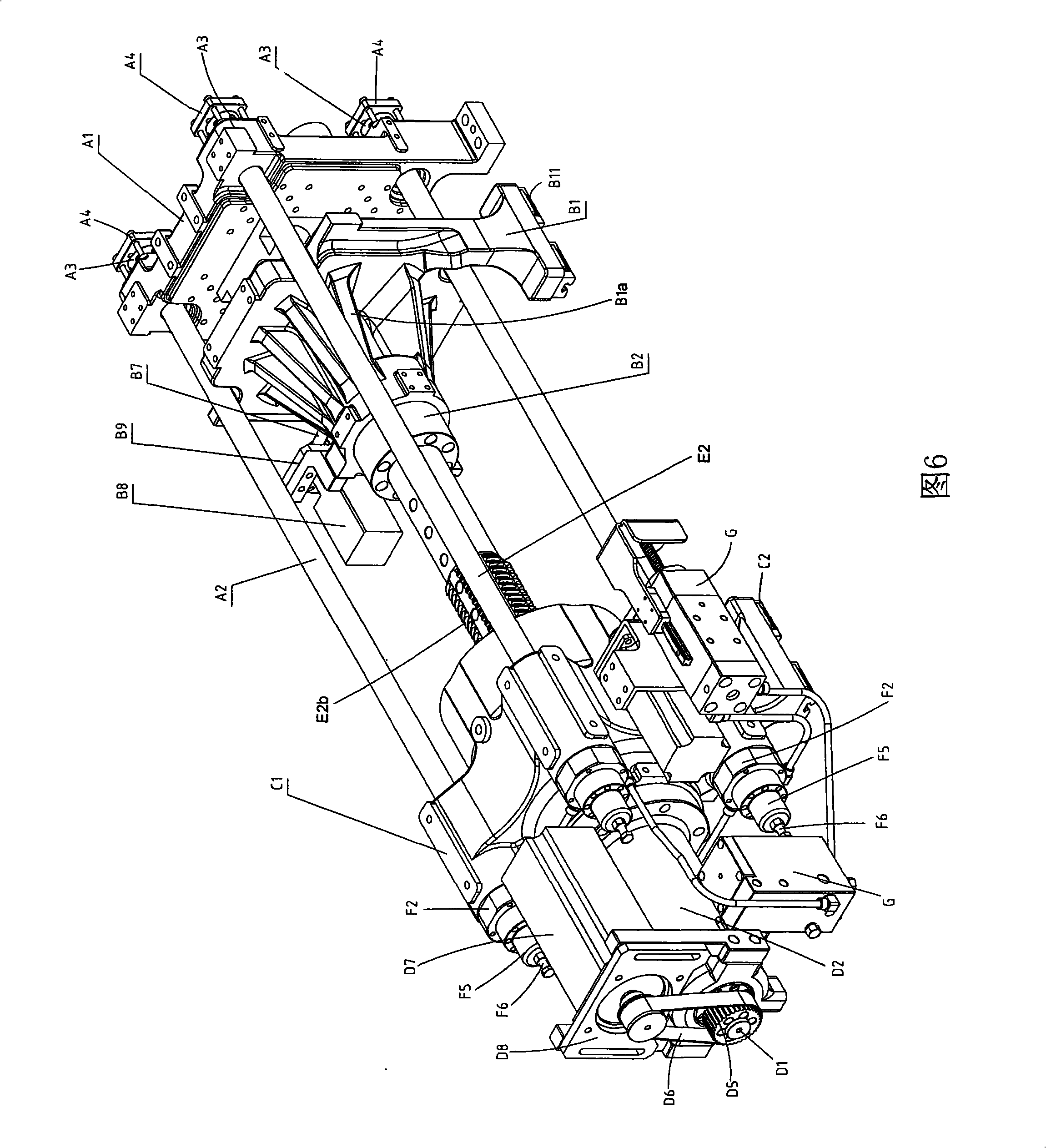
[0028] The present invention will be further described in detail below in conjunction with the accompanying drawings and embodiments.

[0029] Such as Figure 1 to Figure 6As shown, the icon numbers are as follows: front template A1, tie rod A2, tie rod nut A3, tie rod gland A4, middle template B1, horn-shaped body B1a, ejection chamber B1b, inner and outer ring body B2, ejection ball screw B3, Eject the ball screw nut B4, limit block B5, eject the timing belt pulley B6, eject the timing belt B7, eject the motor B8, eject the motor fixing plate B9, the third bearing B10, the first linear guide rail B11, Rear template C1, second linear guide C2, mold moving ball screw D1, protective oil cylinder D2, mold moving ball screw nut D3, mold moving ball screw gland D4, mold moving timing belt pulley D5, mold moving timing belt D6, mold moving motor D7, mold moving motor fixing plate D8, first bearing D9, spindle nut E1, spindle E2, through hole E2a, concave-convex tooth body E2b, fir...


PUM


Abstract

The invention discloses a mould locking device for an electric injection molding machine, which comprises a front moulding plate, a middle moulding plate and a back moulding plate which are arranged sequentially from front to back in parallel, wherein four pull rods are arranged between the front moulding plate and the back moulding plate, and the front ends of the pull rods are fixedly connectedwith the front moulding plate. The tail ends of the pull rods are connected with a mould locking piston, and an outer ring of the mould locking piston is glidingly matched with a mould locking oil cylinder which is fixedly connected with the back moulding plate. The back moulding plate is matched with at least one set of hydraulic jacks, and controls the movement of the mould locking piston. A mould moving motor which is matched on the back moulding plate is connected with a mould moving roll ball screw rod which is positioned in the center of the back moulding plate by driving. The front endof the mould moving roll ball screw rod is fixedly connected with the back end of the middle moulding plate through a main shaft, wherein the back end of the middle moulding plate adopts a horn-shaped structure, and the middle stressing and force transferring effect is uniform. The back moulding plate is provided with a mould adjusting component, a mould locking component and a quick mould movingcomponent integrally, and the structure is compact. The mould moving roll ball screw rod and the main shaft adopt a thread pitch multi-head roll ball screw rod structure, and the mould moving speed is high.

Description

technical field [0001] The invention relates to the technical field of mold locking mechanisms in plastic machinery, in particular to a mold locking mechanism of an electric injection molding machine. Background technique [0002] The mold clamping mechanism of the traditional hydraulic injection molding machine adopts the mold clamping mechanism with double crankshafts and five hinges straight and inclined; this mold clamping mechanism has the advantages of large force amplification ratio, easy design, easy manufacture and relatively low cost. It is widely used. According to incomplete statistics, the proportion of this structure used in China is as high as 90%, and it has irreplaceable advantages. With the continuous improvement of product requirements and the continuous development of electronic aviation, medical treatment, food and plastic raw materials, the traditional hydraulic crankshaft injection molding machine can no longer meet the development of the times. [00...

Claims


Application Information

Patent Timeline
Patent Type & Authority Patents(China)
IPC IPC(8): B29C45/68
Inventor 杨欣坚
Owner NINGBO HAIXING MACHINERY MFG
Why Eureka
Try Eureka