Double computer hot standby automatic neutral-section passing device

An automatic over-phase, dual-machine hot-standby technology is applied in transportation and packaging, vehicle route interaction equipment, railway car body components, etc. Achieve the effect of improving work performance and safety factor, ensuring operational safety, and realizing fully automated control

Inactive Publication Date: 2009-07-22
温应群
View PDF0 Cites 13 Cited by
  • Summary
  • Abstract
  • Description
  • Claims
  • Application Information

AI Technical Summary

Problems solved by technology

[0003] The existing GFX series vehicle-mounted automatic phase separation system lacks the necessary redundancy and status monitoring. At the same time, due to the use of coil-type induction signal receivers, some serious defects have been exposed through the promotion and application in recent years:
[0004] 1. The GFX series automatic over-phase separation system adopts a stand-alone system with PLC as the core, and the reliability of operation cannot be guaranteed. After the interface circuit board or PLC fails, the automatic over-phase separation system will fail. At this time, the locomotive over-phase separation can only It completely relies on the manual operation of the crew. If the system fails during the locomotive operation, it is easy to cause the crew to operate too quickly and cause traffic accidents, which poses a great safety hazard.
For this reason, many locomotive depots use it as an auxiliary support equipment for over-phase separation, and still adopt the control mode of manual over-phase separation, and cannot completely rely on it to realize automatic over-phase control
[0005] 2. The GFX series automatic over-phase separation system uses a mechanical relay to control the output

Method used


Image

  • Double computer hot standby automatic neutral-section passing device
  • Double computer hot standby automatic neutral-section passing device
  • Double computer hot standby automatic neutral-section passing device

Examples


Example Embodiment

[0061] The present invention will be further described below with reference to the drawings and embodiments.

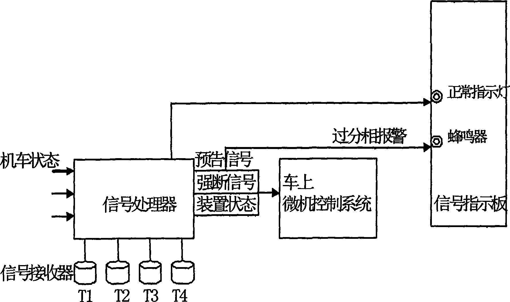
[0062] Such as figure 1 A dual-machine hot standby type automatic phase passing device shown includes a signal processor, a signal receiver and a signal indicating board.

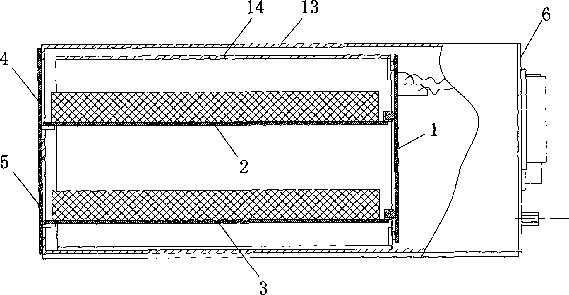
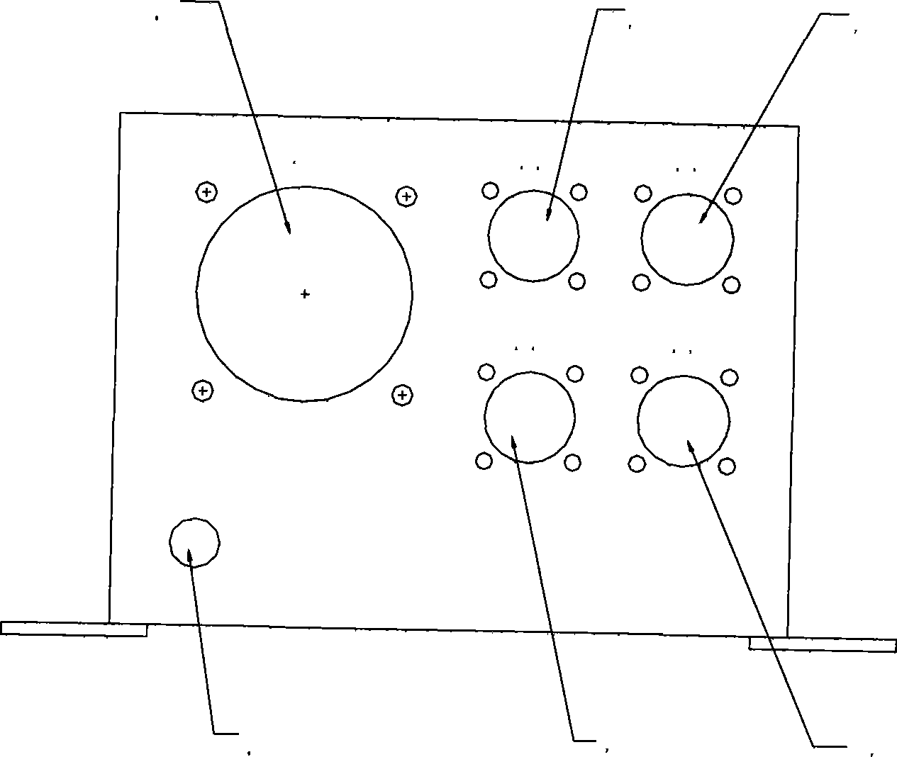
[0063] Such as figure 2 As shown, the signal processor is provided with a circuit connection base plate 1 and two main control circuit boards 2, 3, and the circuit connection base plate 1 is electrically connected to the two main control circuit boards 2, 3 respectively. The front end of the signal processor There are two display and operation panels 4, 5, the two display and operation panels 4, 5 are respectively connected to the two main control circuit boards 2, 3 circuits; the rear end of the signal processor is provided with an external connection socket 6, which is externally connected to the socket 6 Connect the signal receiver; there are two signal indicating boards, which are installed on th...


PUM


Abstract

The invention discloses a double hot spare type automatic passing phase separating device, comprising a signal processor, a signal receiver and signal indicator boards. The signal processor is internally provided with a circuit connecting base board and two main control circuit boards; the circuit connecting base board and the two main control circuit boards are respectively connected by a circuit; the front end of the signal processor is provided with two displaying and operating panels, which are respectively connected with the two main control circuit boards by the circuit; the rear end of the signal processor is provided with a connecting socket which is connected with the outside and is connected with the signal processor; and the number of the signal indicator boards is two and the two signal indicator boards are respectively arranged at two driver positions and are connected with the signal processor after being connected in parallel. The double hot spare type automatic passing phase separating device is applicable to automatic control field of high-speed motor train units and electrical locomotives of electric railways, actually realizes reliable and safe automatic passing phase separating of high motor train units and electrical locomotives and guarantees the safe operation of the high-speed electric railways.

Description

technical field [0001] The invention relates to the field of automatic control of high-speed EMUs and electric locomotives of electrified railways, in particular to a dual-machine hot-standby automatic phase separation device. Background technique [0002] High-speed and heavy-haul is the development direction of China's railways. With the increase of train speed and the continuous extension of electrified railway operation mileage, the requirements for the safety operation standards of rolling stock are getting higher and higher. Therefore, the safe, accurate and reliable passage of electric locomotives through the phase-separation interval has also attracted more and more attention. focus on. For this reason, starting from the construction of the six trunk line speed-raising safety demonstration lines, the Ministry of Railways has listed the electric locomotive on-board automatic phase separation system as the electric locomotive safety technical equipment. Its main func...

Claims


Application Information

Patent Timeline
IPC IPC(8): B61L1/20B60M3/00
Inventor 温应群
Owner 温应群
Why Eureka
Try Eureka