
Constant current source control circuit

A control circuit and constant current source technology, applied in energy-saving control technology, lamp circuit layout, light source, etc., can solve the problems of lower reliability, difficult implementation, difficult control, etc., and achieve the effect of improving efficiency, reducing cost, and simple structure

Inactive Publication Date: 2012-04-04
MOSO POWER SUPPLY TECH
View PDF0 Cites 0 Cited by
  • Summary
  • Abstract
  • Description
  • Claims
  • Application Information

AI Technical Summary

Problems solved by technology

[0004] The existing constant current power conversion circuit has low efficiency, complex circuit, not easy to control, and limited range of application, etc., which affect its use
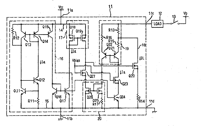
In the existing technology, such as figure 1 Shown is a constant current device (US.Patent NO.6954058B2, On OCt, 11, 2005), the circuit is complicated, difficult to realize, and high in cost
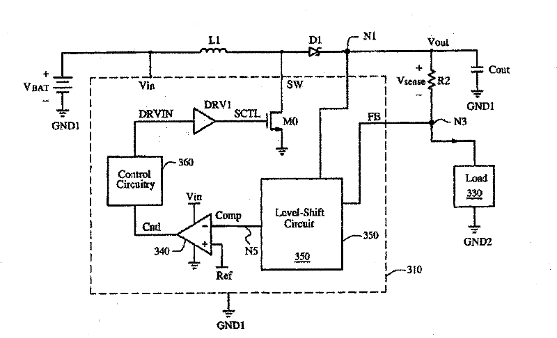
like figure 2 The converter shown as feedback voltage and reference output voltage (US.Patent NO.7317302 B1, On Jan, 8, 2008) is a constant voltage output, which limits its application range
[0005] For the Buck converter with floating output, its general constant current control method needs to obtain a constant output current by sampling the output current, and it is necessary to add an isolation amplifier circuit such as an optocoupler to amplify the current signal, which will increase the cost and circuit complexity, reduces reliability

Method used


Image

  • Constant current source control circuit
  • Constant current source control circuit
  • Constant current source control circuit

Examples


Embodiment Construction

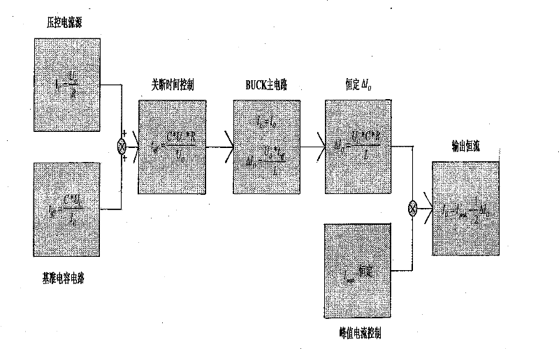
[0027] Refer to attached Figure 4 (a)-4(d), curve 4(a) is the waveform of the gate voltage of the switching tube, curve 4(b) is the waveform of the inductor current under CCM, curve 4(c) is the waveform of the reference capacitor voltage, curve 4(d) It is the inductor current waveform under BCM. where I o is the average value of the output current, I peak is the maximum output current, I val is the minimum output current, ΔI o is the amount of output current ripple. at t on Time, the switch tube is turned on, the reference capacitor discharges, its voltage drops rapidly, and the inductor current rises to I peak , the switch is turned off. At this time, the switch tube turns from on to off, and the output current reaches the peak value I peak . at t off During the time, the voltage-controlled current source charges the reference capacitor, and the reference capacitor voltage rises to U C (U C is the reference capacitor voltage reference value), the switch tube is tur...


PUM


Abstract

The present invention discloses a constant-current source control circuit which comprises a main circuit, a reference condenser circuit, a voltage control current source circuit and a switch tube control circuit. The invention is characterized in that the main circuit is a power conversion circuit which comprises an inductor L1, an inductive current detecting resistor SR1 and a first switch tube SQ1. The reference capacitor circuit comprises a reference capacitor SC3 and a second switch tube SQ3. The voltage control current source circuit is used for charging the reference capacitor SC3 and has a current magnitude which is proportional with the output voltage U0. The switch tube control module synchronously controls the switching of the first switch tube SQ1 and the second switch tube SQ3, and controls the product of output voltage U0 and the switching time toff of switch tube to a constant number. The constant-current source control circuit of the invention has the advantages of simple structure, low cost, high efficiency, etc.

Description

technical field [0001] The invention relates to a control circuit of a constant current source. More specifically, the present invention relates to a control and drive circuit for a constant current source for driving LEDs. Background technique [0002] With the development and maturity of high-power LED technology, the performance index of LED for lighting has been greatly improved day by day. At present, the luminous efficiency of industrialized white LEDs has reached (70-90) lm / W, far exceeding the luminous efficiency level of ordinary incandescent lamps. High-power LEDs will be more and more widely used in the field of lighting. It is the fourth-generation lighting source that replaces fluorescent lamps and incandescent lamps in the 21st century. [0003] Since the LED lamp has a large voltage variation range according to the number of LEDs, and the driving current of the LED can only obtain high light efficiency and long life if the driving current is constant, so the...

Claims


Application Information

Patent Timeline
Patent Type & Authority Patents(China)
IPC IPC(8): H05B37/02
CPCY02B20/42Y02B20/40
Inventor 吴新科裴倩陈首先华桂潮
Owner MOSO POWER SUPPLY TECH
Learn More