

Variable magnetic flux motor drive system
A magnetic flux motor and driver technology, which is applied in the direction of motor generator control, electromechanical brake control, AC motor control, etc., can solve the problems of increased capacity of switching elements, increased current capacity of switching elements, and increased costs, so as to prevent the application of Effects of braking force, suppression of deterioration of torque accuracy, and improvement of efficiency
- Summary
- Abstract
- Description
- Claims
- Application Information
AI Technical Summary
Problems solved by technology
Method used
Image

Examples
no. 1 approach
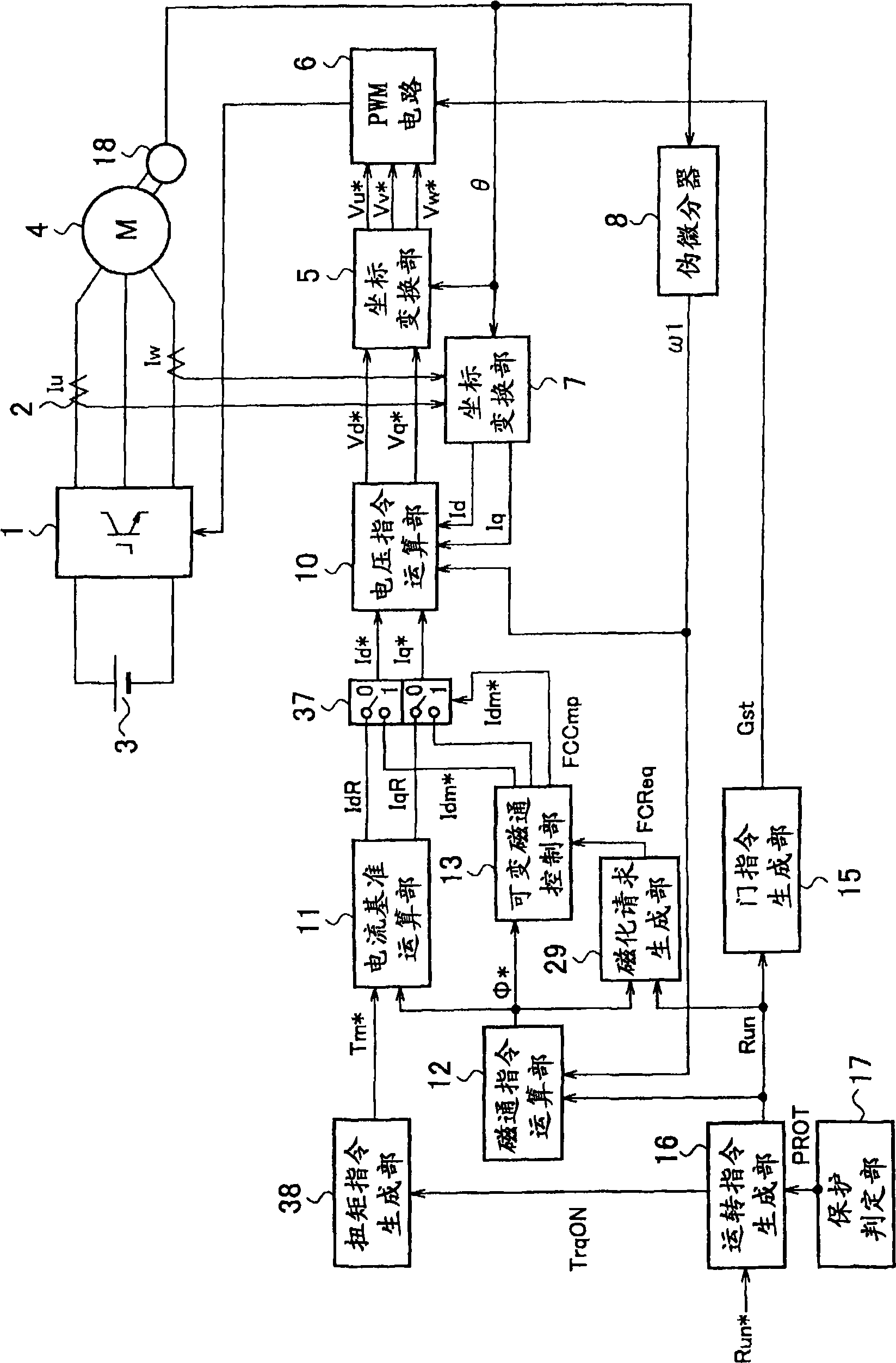
[0098] figure 1 It is a block diagram of the variable magnetic flux motor drive system of 1st Embodiment of this invention. First, the main circuit including the variable magnetic flux motor 4 of the drive system will be described. Inverter 1 converts DC power from a DC power supply into AC power and supplies it to variable magnetic flux motor 4 . Currents Iu and Iw supplied to variable magnetic flux motor 4 are detected by current detector 2 and converted into D-axis current Id and Q-axis current Iq by coordinate conversion unit 7 and input to voltage command calculation unit 10 . The D-axis voltage command Vd from the voltage command calculation unit 10 * , Q-axis voltage command Vq * is input to the coordinate converter 5 and converted into a three-phase voltage command Vu * 、Vv * 、Vw * Then input to PWM circuit 6. The PWM circuit 6 controls the switching elements of the inverter 1 to be turned on and off using the gate command Gst from the gate command generator 15...
no. 2 approach
[0176] Figure 10 It is a block diagram of the variable magnetic flux motor drive system of 2nd Embodiment of this invention. In this second embodiment, relatively figure 1 In the first embodiment shown, the magnetization request generation unit 29 generates the front-stage magnetization request flag FCReq 0 output to the torque command generation unit 38 instead of the magnetization request flag FCReq output to the variable magnetic flux control unit 13, and the torque command generation unit 38 In addition to the torque permission flag TrqON, also input the previous stage magnetization request flag FCReq 0 and the magnetization completion flag FCCmp, in addition to the torque command Tm * In addition, a magnetization request flag FCReq is also generated. That is, the torque command generator 38 generates a torque command Tm that reduces the torque when the variable magnet is magnetized. * , and outputs the magnetization request flag FCReq to the variable magnetic flux co...
no. 3 approach
[0187] Figure 13 It is a block diagram of the variable magnetic flux motor drive system of 3rd Embodiment of this invention. In this third embodiment, relatively figure 1 In the first embodiment shown, a modulation rate calculation unit 61 and a field weakening control unit 62 are additionally provided, and an output signal of the field weakening control unit 62 is input to the magnetization request generation unit 29 . Thus, the magnetization request generator 29 generates a magnetization request according to the modulation factor of the inverter 1 . right with figure 1 The same reference numerals are attached to the same elements, and repeated explanations are omitted.
[0188] exist Figure 13 Among them, the DC-side voltage Vdc of the inverter 1 is detected by the DC voltage detector 60 and input to the modulation factor computing unit 61 . The DQ-axis voltage command Vd, which is the output of the voltage command calculation unit 10, is also input to the modulatio...
PUM
 Abstract
Description
Claims
Application Information