Supercharge Your Innovation With Domain-Expert AI Agents!

Support pin

A technology of support pins and arms, applied in optics, instruments, nonlinear optics, etc., can solve the problems of time-consuming and labor-intensive, difficult dismantling, etc., and achieve the effects of reducing volume, solving cost consumption, and reducing the cost of consumables

Inactive Publication Date: 2009-07-29
CPT TECH GRP +1
View PDF0 Cites 1 Cited by
  • Summary
  • Abstract
  • Description
  • Claims
  • Application Information

AI Technical Summary

Problems solved by technology

[0007] However, the body 52, which is more than 18 centimeters long, accounts for almost 90% of the length of the entire support pin 50. It not only penetrates into the electrode seat 22 and the base 14, it is not easy to remove, and when replacing the support pin 50, the base 14 needs to be removed first. Only the tubular elements (Bellows) (not shown) in the support pin 50 can be replaced, and after the replacement is completed, it is necessary to reassemble and calibrate the entire base 14 and the dry etching device, which is very time-consuming and labor-intensive.

Method used


Image

  • Support pin
  • Support pin
  • Support pin

Examples


Embodiment Construction

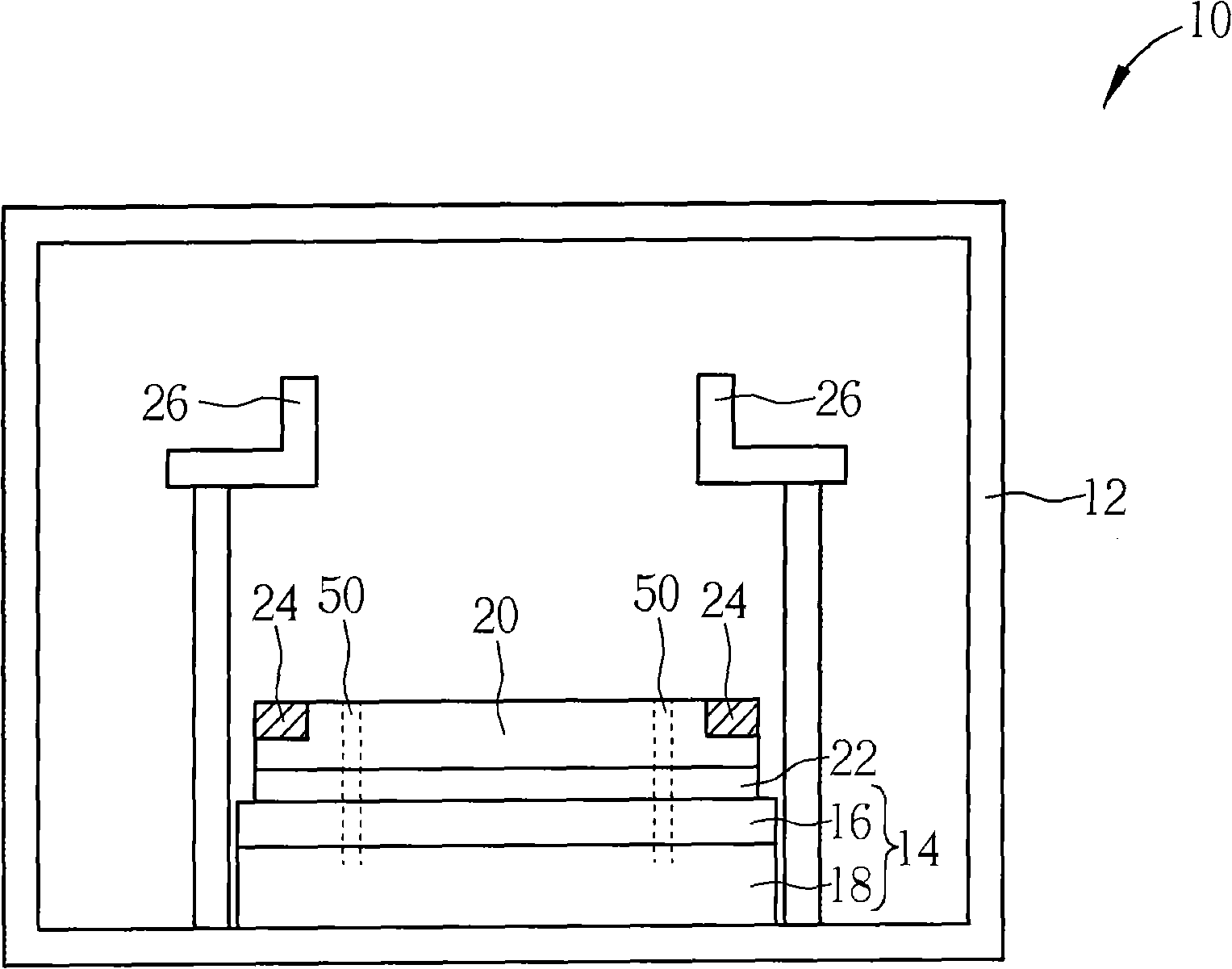
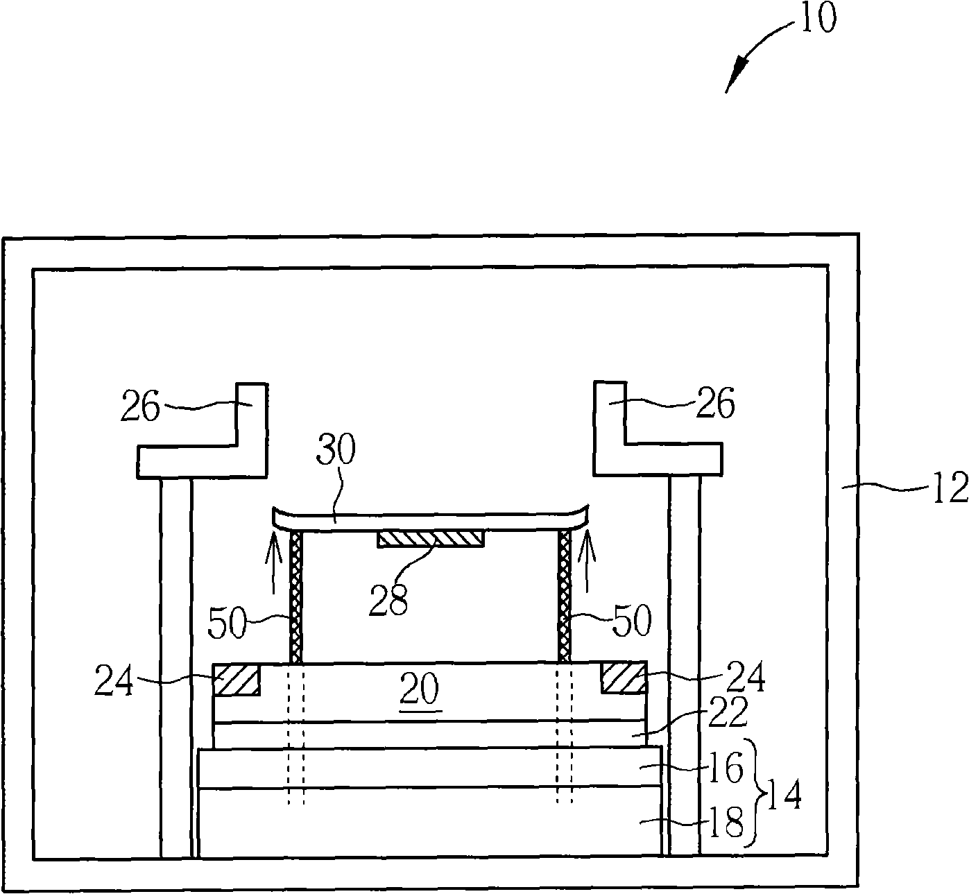
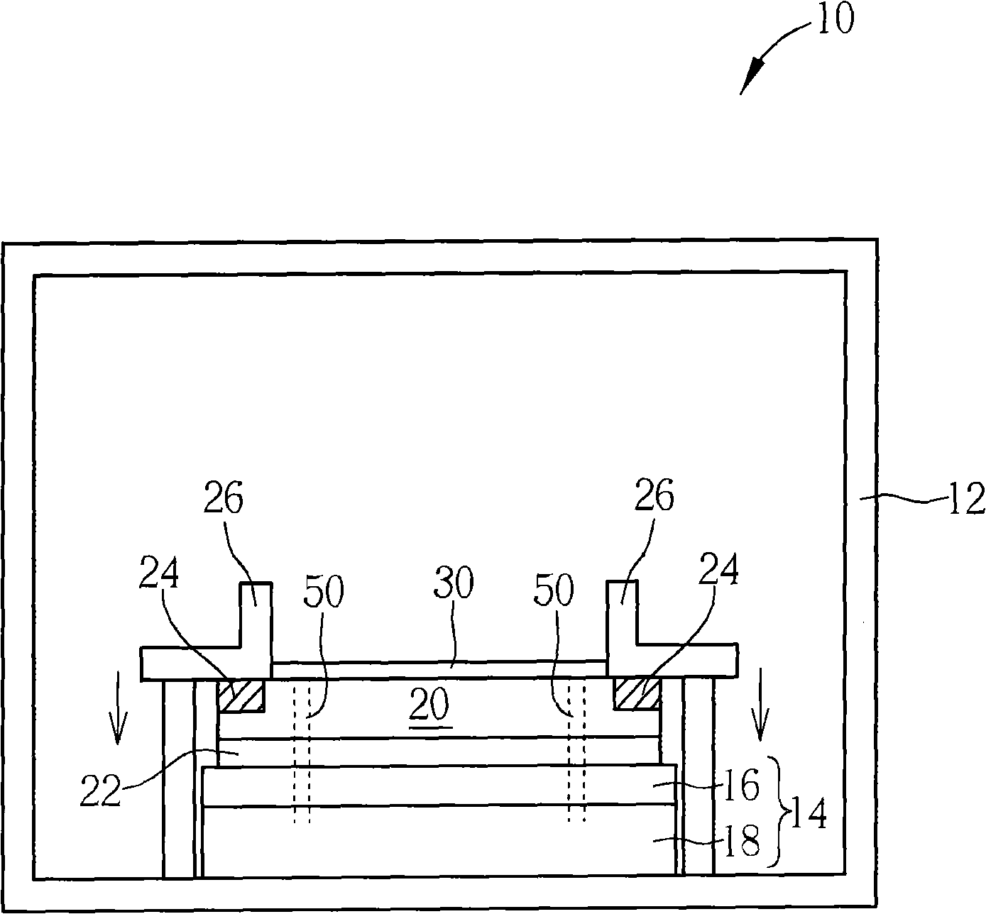
[0027] Please refer to Figure 6 to Figure 9 , FIG. 6 is a schematic diagram of a support pin in a preferred embodiment of the present invention, Figure 7 to Figure 9 It is an exploded structure diagram of various parts of the support pin in the preferred embodiment of the present invention. As shown in Figure 6, the support pin 60 of the preferred embodiment of the present invention is a three-piece structure, which includes three parts such as a body 62, an arm 64 and a solid lock seat 66, and all The detachable way is vertically socketed and combined to fit and fix each other, and connected to become the support pin 60 of the present invention. Wherein, according to the vertical direction, the support arm 64 is detachably disposed on the top of the locking seat 66 , and the body 62 is detachably disposed on the top of the support arm 64 .

[0028] like Figure 7 As shown, the bottom end 67 of the locking seat 66 has a groove 63, and the inner wall of the groove 63 has a...


PUM


Abstract

The invention provides a supporting pin applied to a dry etching device, which comprises a fixed lock base, a body and a supporting arm, wherein the supporting arm is detachably fixed at the top end of the fixed lock base, and the body is detachably fixed at the top end of the supporting arm. The supporting pin has the advantages that the supporting pin reduces the volume of a part to be replaced due to the design of detachable assembly of the three components of the supporting pin, not only reduces consumptive material cost, but also is easy to carry out maintenance work such as detachment, replacement, and the like so as to effectively solve the problem of unnecessary cost consumption caused by the replacement of consumptive materials in a current dry etching machine station.

Description

【Technical field】 [0001] The invention relates to a support pin, in particular to a support pin applied to a dry etching device. 【Background technique】 [0002] At present, dry etching devices such as plasma etching apparatuses have been widely used in the production process of liquid crystal display panels to remove the masking layer not covered by the patterned shielding layer such as photoresist. And protected parts to transfer the mask pattern (pattern) to the specific film on the surface of the glass substrate. Plasma etching mainly uses plasma to dissociate reactive gas molecules into ions that are reactive to the film material on the surface of the glass substrate, so as to chemically react with the film on the glass substrate, and then make the particles exposed to the plasma The film is etched and reacted into volatile substances, and then the volatile substances generated by the reaction are extracted from the surface of the glass substrate by a vacuum system. ...

Claims


Application Information

Patent Timeline
IPC IPC(8): C03C15/00G02F1/1333
Inventor 湛仁宗
Owner CPT TECH GRP
Features
  • R&D
  • Intellectual Property
  • Life Sciences
  • Materials
  • Tech Scout
  • Unparalleled Data Quality
  • Higher Quality Content
  • 60% Fewer Hallucinations
Learn More