Parallel flow evaporator core structure

An evaporator core and parallel flow technology, applied in evaporators/condensers, refrigeration components, refrigerators, etc., can solve the problems of small number of pipelines, small total cross-sectional area, small heat dissipation area, etc.

Inactive Publication Date: 2009-07-29
HANGZHOU SUNHOLD INDAL
View PDF0 Cites 2 Cited by
  • Summary
  • Abstract
  • Description
  • Claims
  • Application Information

AI Technical Summary

Problems solved by technology

[0002] The core body of the existing air conditioner evaporator, which is used to dissipate heat and circulate the refrigerant, is connected with the liquid distribution pipe of the liquid distributor assembly in parallel with a plurality of serpentine single-hole pipes or pipe strips, and the refrigerant is circulated at the same time. However, due to the small number of pipelines circulating refrigerant at the same time and the total cross-sectional area is small, the flow rate of refrigerant in the heat dissipation pipe is also small, and because of the serpentine heat dissipation pipe, the pipe wall is thicker, In addition, the total heat dissipation area is small, and the refrigerant is circulated in reverse for many times, so that the heat dissipation effect of the refrigerant in the serpentine heat dissipation pipe is poor
These deficiencies are still very prominent on the core body of the existing air conditioner evaporator

Method used


Image

  • Parallel flow evaporator core structure
  • Parallel flow evaporator core structure
  • Parallel flow evaporator core structure

Examples


Embodiment Construction

[0028] The present invention will be further described below in conjunction with the accompanying drawings and embodiments.

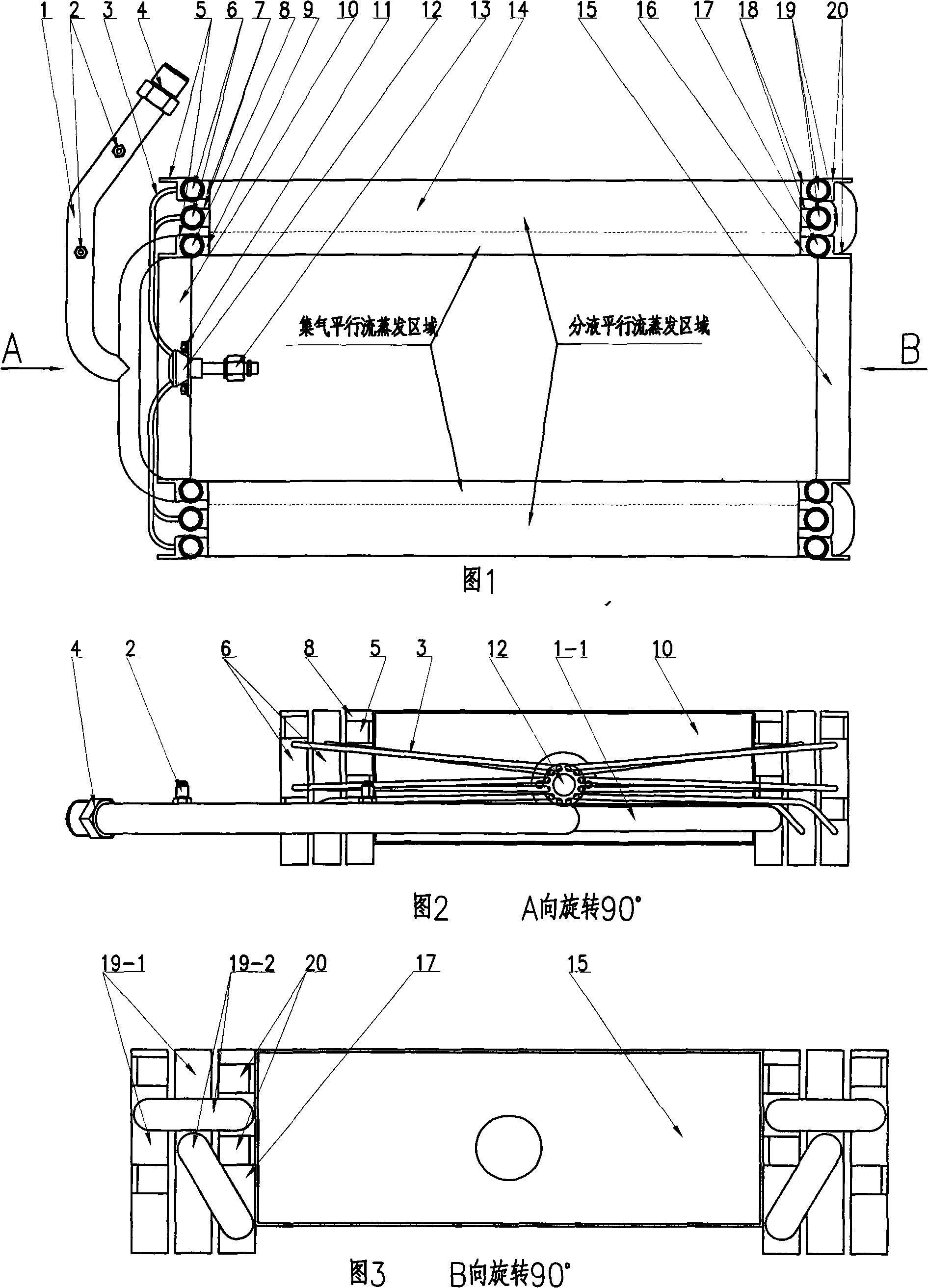
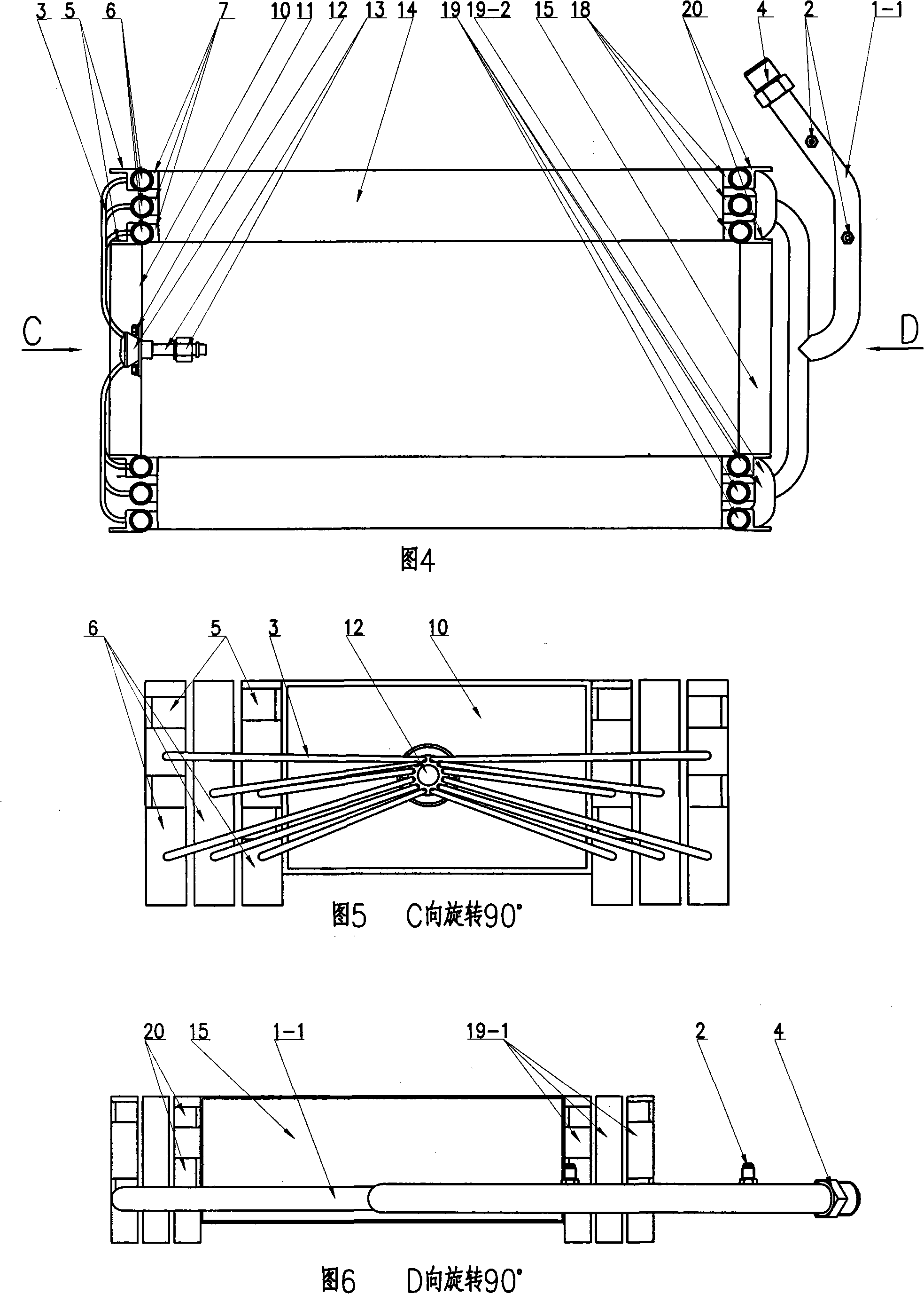
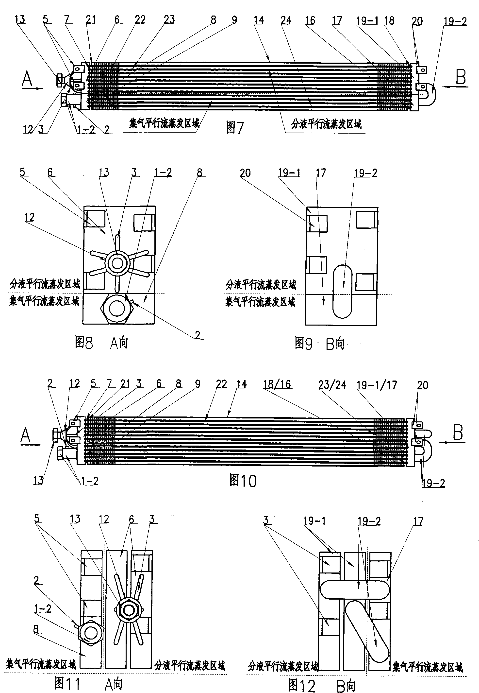
[0029] The structure of the core body of the parallel flow evaporator includes the unit shown in Figure 7 and Figure 8 and Figure 9, Figure 10 and Figure 11 and Figure 12, Figure 13 and Figure 14 and Figure 15, Figure 16 and Figure 17 and Figure 18 The structure of the parallel flow evaporator core, and the structure of the parallel parallel flow evaporator core shown in Figure 1 and Figure 2 and Figure 3, Figure 4 and Figure 5 and Figure 6.

[0030] Construction of a single piece parallel flow evaporator core.

[0031] Separate the components first, and form a single parallel flow evaporator as shown in Figure 7 and Figure 8 and Figure 9, Figure 10 and Figure 11 and Figure 12, Figure 13 and Figure 14 and Figure 15, Figure 16 and Figure 17 and Figure 18 The parts of the device core body are divided into radiators, liquid separators 12, gas collection t...


PUM


Abstract

The invention provides a parallel flow evaporator core structure. A single parallel flow evaporator core thereof is equipped with a radiator, a tritorium, a gas collector and a reverse communicating gas separating tank and a return pipe and also uses a thin-wall parallel flow pipe band; a parallel type parallel flow evaporator core is formed by integrating a plurality of single parallel flow evaporator cores. Full liquid separation-gas collection, non-reverse parallel circulating refrigerant can be carried out in a full liquid separation parallel flow evaporation area, or, liquid separation-gas collection and gas separation-gas collection, reverse refrigerant circulating among parallel flow evaporating areas by the reverse communicated gas separating tank can be carried out in liquid separating parallel flow evaporating area and gas collecting parallel flow evaporating area according to the collecting-separating ratio. The invention effectively shortens the pipeline of the circulating refrigerant, increases the pipeline number, total cross sectional area and gross evaporation area of the circulating refrigerant, thus obviously improving the evaporation efficiency and reducing the production cost and energy consumption for the evaporator core. The technique scheme not only can further improve and upgrade the air conditioner evaporator technology and product, but also can improve economic benefit and save energy.

Description

Technical field: [0001] The invention relates to air-conditioning technology, in particular to core body technology of an air-conditioning evaporator. Background technique: [0002] The core body of the existing air conditioner evaporator, which is used to dissipate heat and circulate the refrigerant, is connected with the liquid distribution pipe of the liquid distributor assembly in parallel with a plurality of serpentine single-hole pipes or pipe strips, and the refrigerant is circulated at the same time. However, due to the small number of pipelines circulating refrigerant at the same time and the total cross-sectional area is small, the flow rate of refrigerant in the heat dissipation pipe is also small, and because of the serpentine heat dissipation pipe, the pipe wall is thicker, Moreover, the total heat dissipation area is relatively small, and the refrigerant is reversely circulated many times, so that the heat dissipation effect of the refrigerant in the serpentine...

Claims


Application Information

Patent Timeline
Patent Type & Authority Applications(China)
IPC IPC(8): F25B39/02
Inventor 冯金祥冯罗平徐国林
Owner HANGZHOU SUNHOLD INDAL
Why Eureka
Try Eureka