Method for manufacturing commutator

A manufacturing method and commutator technology, applied in commutator manufacturing and other directions, can solve the problems of residual mica, easy to cause oblique sheets, long production cycle, etc., so as to reduce production processes and equipment, ensure forming size, and improve work efficiency. Effect

Inactive Publication Date: 2009-07-29
HUARUI ELECTRICAL APPLIANCE
View PDF0 Cites 19 Cited by
  • Summary
  • Abstract
  • Description
  • Claims
  • Application Information

AI Technical Summary

Problems solved by technology

[0004] In the above-mentioned manufacturing method, after the commutator is turned, the insulating groove provided with the mica sheet needs to be milled according to the regulations, the subsequent processing technology involved is relatively complicated, and the production cycle is long; in addition, there is such a problem in the processing of the insulating groove: due to There is a certain tolerance in the processing and f

Method used


Image

  • Method for manufacturing commutator
  • Method for manufacturing commutator
  • Method for manufacturing commutator

Examples


Embodiment Construction

[0028] The present invention will be further described in detail below in conjunction with the accompanying drawings and embodiments.

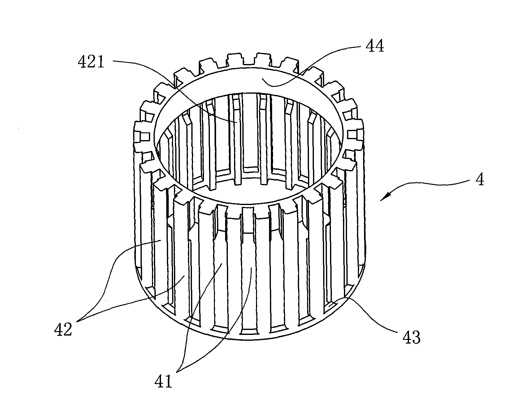
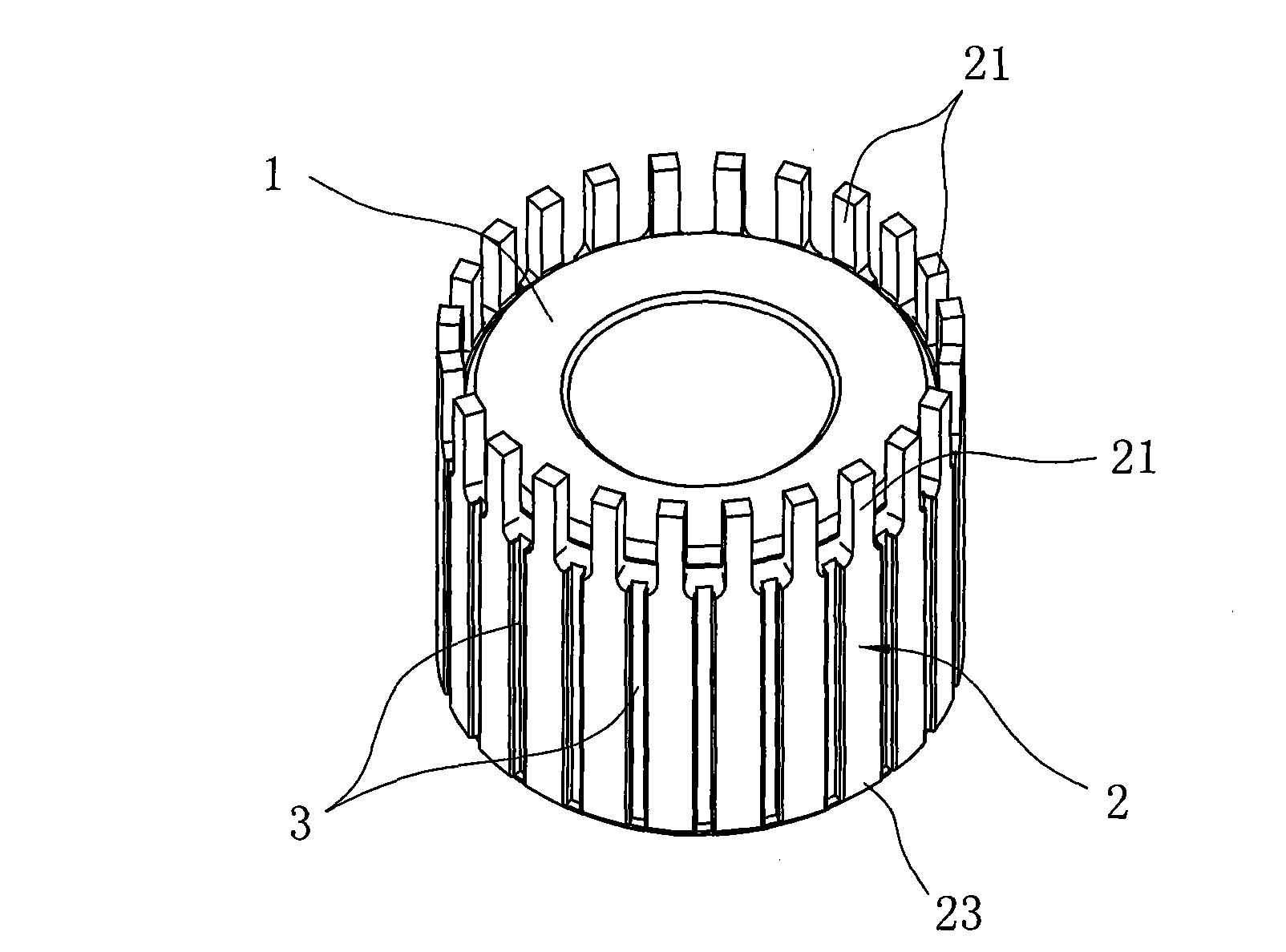
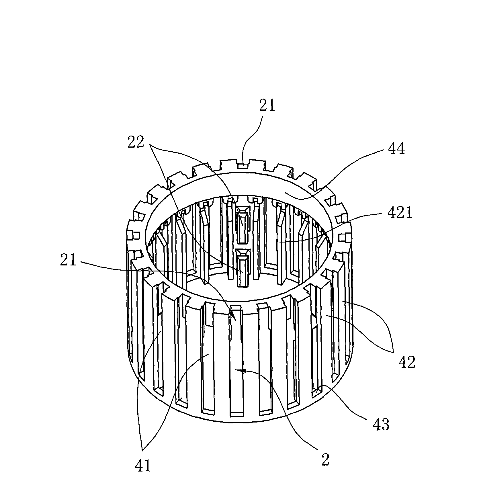
[0029] Such as Figure 1 to Figure 5 As shown, it is a specific embodiment of the present invention. The commutator of this embodiment is a hook-type commutator with a hook foot. The commutator includes a base 1 and a plurality of commutator segments 2 arranged on the circumference of the base. , there are insulating grooves 3 between the commutator pieces 2, wherein the commutator piece 2 is provided with hook feet 21 and dovetail inner ribs 22, the hook feet 21 are made by a die process, and the dovetail inner ribs 22 can expand the base body 1 and the commutator piece 2, the commutator base 1 is made of engineering plastics;

[0030] In this embodiment, the manufacturing method of the commutator includes the following process steps:

[0031] ①. Copper is used as raw material, and the material is cut and drawn into copper bars;

[0032] ②...


PUM


Abstract

The invention discloses a method for manufacturing a commutator, which is characterized by following procedures including: (1) blanking and drawing; (2) punching a commutator segment provided with a hook; (3) washing the commutator segment; (4) lining up the commutator segment which is then pressed and arranged on a locating housing wrapping the inner side of the hook of the commutator segment; (5) sheathing the locating housing on an injection molding die to complete the injection molding of the commutator; (6) removing a feed handle, stripping down the locating housing and forming an insulation groove; (7) curing; (8) machine hinging an inner hole of the commutator; (9) forming a hook of the commutator; and (10) polishing. Compared with the prior art, the insulation groove of the commutator of the invention is completed through forming in one piece of the locating housing; in the process of forming the insulation groove, no mica sheet is used, and mechanical processing such as engraving mica, etc. is not needed; the locating housing can solve the problem of over-tight matching between the molding die and the hook of the commutator segment, and improve yield of the product; simultaneously, wrapping of the commutator segment by the locating housing avoids pasting of plastic on the hook when injection molding is carried out; and a demand for clean surface of the hook can be met without turning.

Description

technical field [0001] The invention relates to a method for manufacturing a commutator, in particular to a method for manufacturing a hook type commutator. Background technique [0002] At present, there are many structures of commutators used in motor armatures, such as slot commutators, hook commutators, K-type commutators, etc. Most products include a commutator base and molded on the commutator. Multiple commutator segments on a base body. For the hook commutator, one end of the commutator segment is provided with a hook foot, and the commutator base is provided with a plurality of insulating grooves equipped with mica sheets. The insulating grooves are formed by machining, generally Turning the outer circle first, and then milling with a milling blade can be completed in multiple processes, and the mica sheet also needs to go through multiple processes such as blanking, punching, sheet arranging, and pressing. The hook commutator in the prior art The manufacturing pr...

Claims


Application Information

Patent Timeline
IPC IPC(8): H01R43/06
Inventor 许刚位
Owner HUARUI ELECTRICAL APPLIANCE
Why Eureka
Try Eureka