Synchronous commutation control device and forward type synchronous commutation circuit

A technology of synchronous rectification and control devices, which is applied in control/regulation systems, output power conversion devices, DC power input conversion to DC power output, etc. It can solve the problems of current reverse flow and achieve the effect of avoiding reverse flow phenomenon

Inactive Publication Date: 2009-07-29
NIKO SEMICON
View PDF0 Cites 13 Cited by
  • Summary
  • Abstract
  • Description
  • Claims
  • Application Information

AI Technical Summary

Problems solved by technology

[0009] In view of the disadvantages in the prior art that easily cause current reverse flow in the non-current continuous mode, the synchronous rectification control device of the present invention detects the state of the forward synchronous rectification circuit, and when the forward synchronous rectification circuit enters the non-current continuous mode Stopping the switching of synchronous rectification transistor switches to avoid the problem of current reverse flow

Method used


Image

  • Synchronous commutation control device and forward type synchronous commutation circuit
  • Synchronous commutation control device and forward type synchronous commutation circuit
  • Synchronous commutation control device and forward type synchronous commutation circuit

Examples


Embodiment Construction

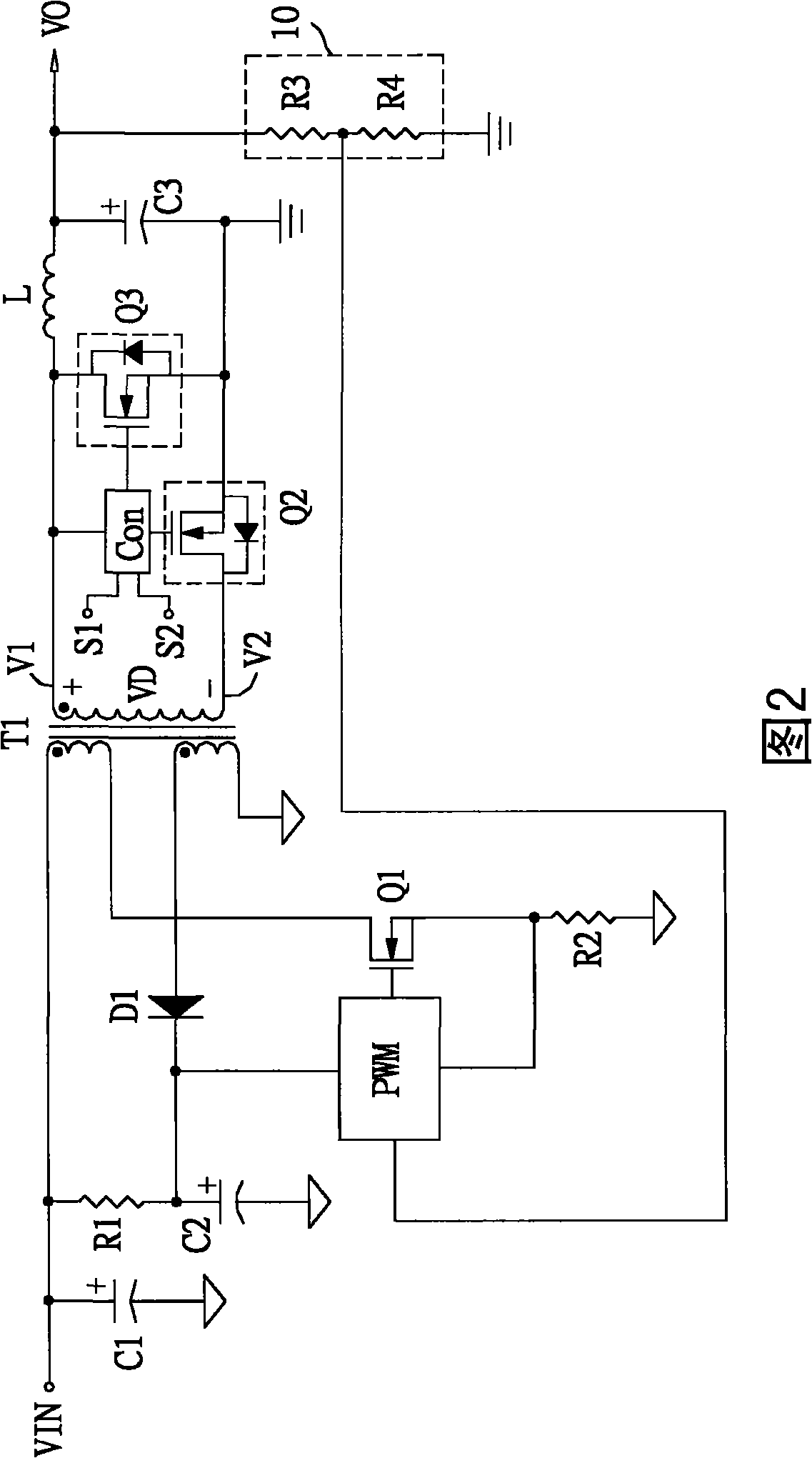
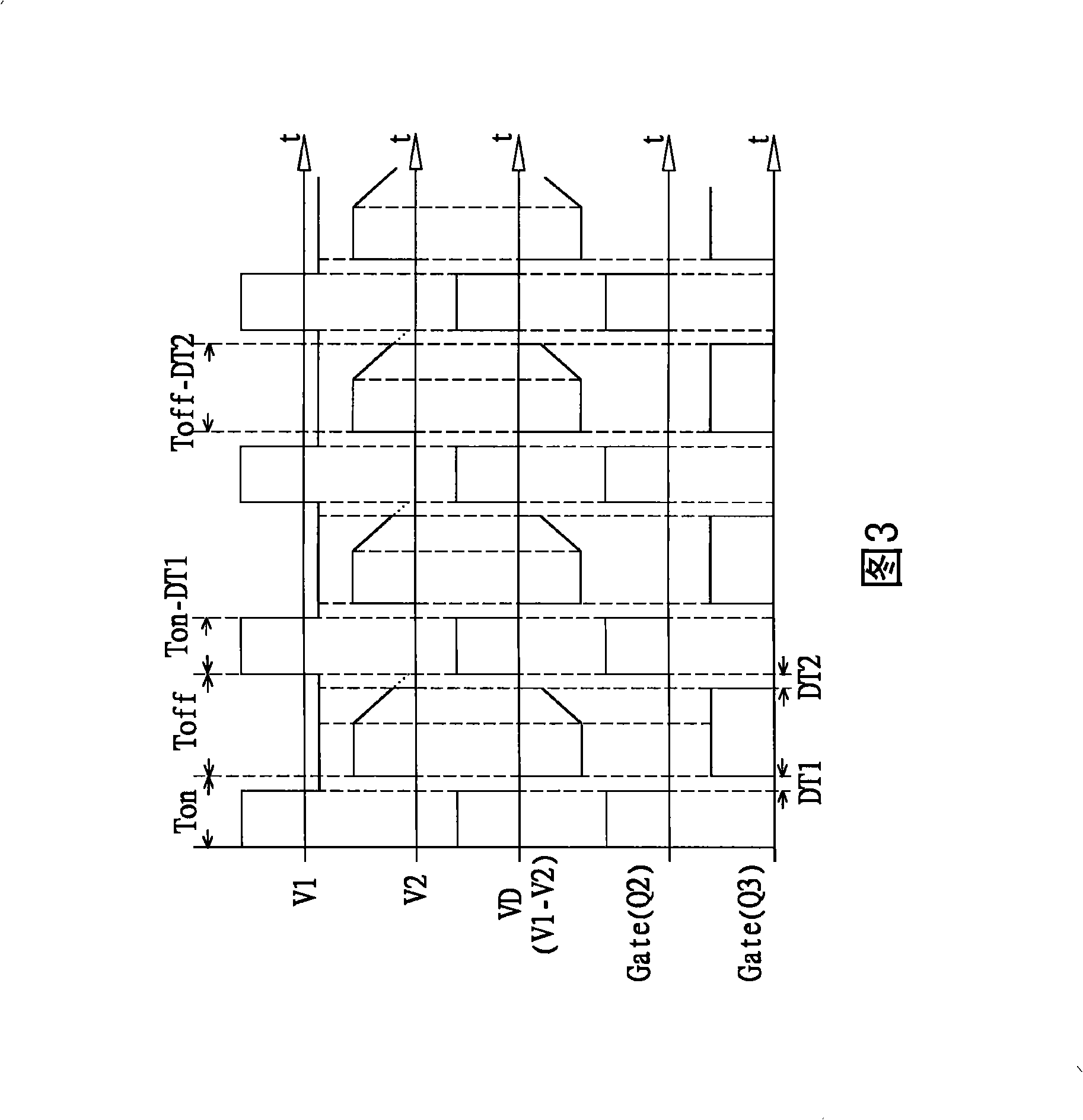
[0063] The present invention uses a time reference circuit to compare whether the conduction time of the primary side of the forward synchronous rectification circuit exceeds a predetermined length of time, and if so, it is judged to enter the discontinuous current mode, and the transistor Q3 used for synchronous rectification on the secondary side is stopped. conduction to avoid the occurrence of current reverse flow.

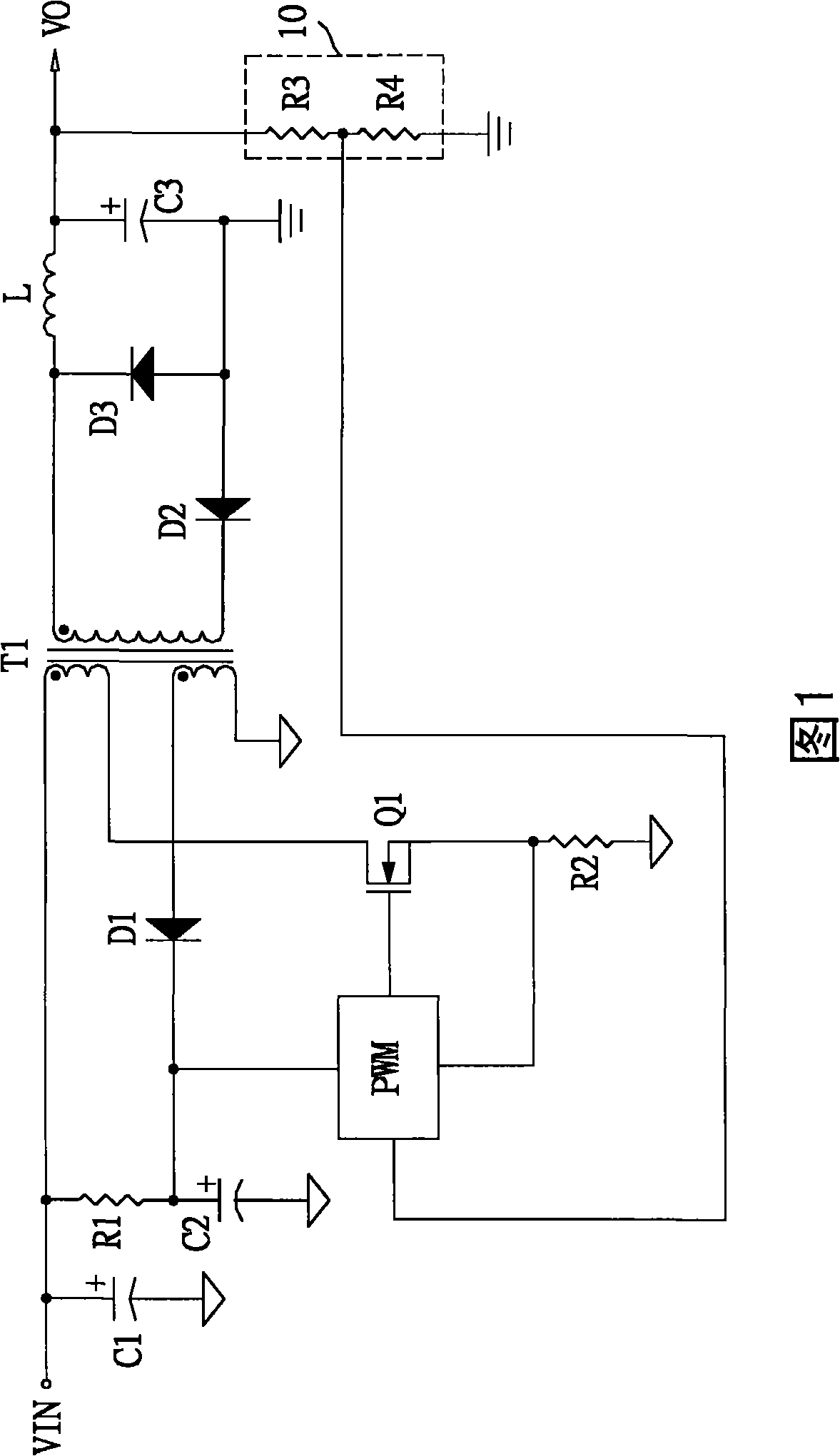
[0064] Please refer to FIG. 5 , which is a schematic diagram of a forward synchronous rectification circuit according to a preferred embodiment of the present invention. The forward synchronous rectification circuit includes an input power supply VIN, a pulse width modulation controller PWM, an input filter capacitor C1, a start-up resistor R1, a start-up capacitor C2, a current detection resistor R2, a rectifier diode D1, a Transistor switches Q1, Q2 and Q3, a transformer T1, an energy storage inductor L, an output filter capacitor C3, a voltage detector 10 a...


PUM


Abstract

The invention provides a synchronous rectifier control device and a forward synchronous rectifier circuit. The synchronous rectifier control device is connected at a secondary side of the forward synchronous rectifier circuit and comprises a state judging device, a time reference circuit and a synchronous signal generator, wherein, the state judging device receives a detection signal representing the state at the secondary side of the forward synchronous rectifier circuit and at least a reference signal and accordingly generates a first synchronous control signal; the time reference circuit is connected with the state judging device and generates a time reference signal according to the first synchronous control signal; and the synchronous signal generator generates a second synchronous control signal according to the first synchronous control signal and the time reference signal. When the time duration of the first synchronous control signal is shorter than that of the time reference signal, the synchronous signal generator stops generating the second synchronous control signal.

Description

technical field [0001] The invention relates to a forward synchronous rectification device and a forward synchronous rectification circuit, in particular to a forward synchronous rectification device and a forward synchronous rectification device for judging a continuous current mode or a discontinuous current mode according to the duty cycle of an input signal. Synchronous rectification circuit. Background technique [0002] FIG. 1 is a schematic diagram of a known forward circuit. The forward circuit is provided with a transformer T1, and its primary side is provided with the input power supply VIN provided by the previous stage circuit, the pulse width modulation controller PWM, the input filter capacitor C1, the starting resistor R1, the starting capacitor C2, and the current detection resistor R2 , the rectifier diode D1 and the transistor switch Q1 controlled by the pulse width modulation device controller PWM. The secondary side of the transformer T1 is provided wit...

Claims


Application Information

Patent Timeline
Patent Type & Authority Applications(China)
IPC IPC(8): H02M3/28H02M3/335
CPCY02B70/1475Y02B70/10
Inventor 林春敏潘信佑
Owner NIKO SEMICON
Why Eureka
Try Eureka