Supercharge Your Innovation With Domain-Expert AI Agents!

Delay-locked loop and a stabilizing method thereof

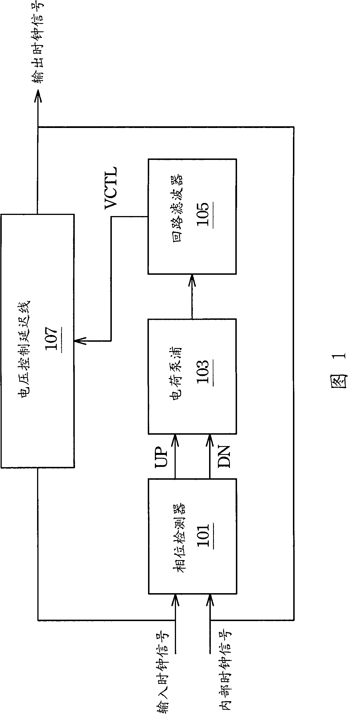
A delay-locked loop and clock signal technology, applied in the direction of electrical components, automatic power control, etc., can solve the problems that the voltage control delay line 107 cannot generate delay time, the chip circuit is unstable, and the clock signal cannot be correctly locked.

Inactive Publication Date: 2009-07-29
HIMAX TECH LTD
View PDF0 Cites 9 Cited by
  • Summary
  • Abstract
  • Description
  • Claims
  • Application Information

AI Technical Summary

Problems solved by technology

[0007] However, in this traditional delay-locked loop, the control voltage VCTL cannot keep up with the fast-changing hysteresis signal UP and the leading signal DN output by the phase detector, so that the voltage-controlled delay line 107 cannot generate the correct delay time, so it cannot be locked correctly clock signal, causing circuit instability on the chip

Method used


Image

  • Delay-locked loop and a stabilizing method thereof
  • Delay-locked loop and a stabilizing method thereof
  • Delay-locked loop and a stabilizing method thereof

Examples


Embodiment Construction

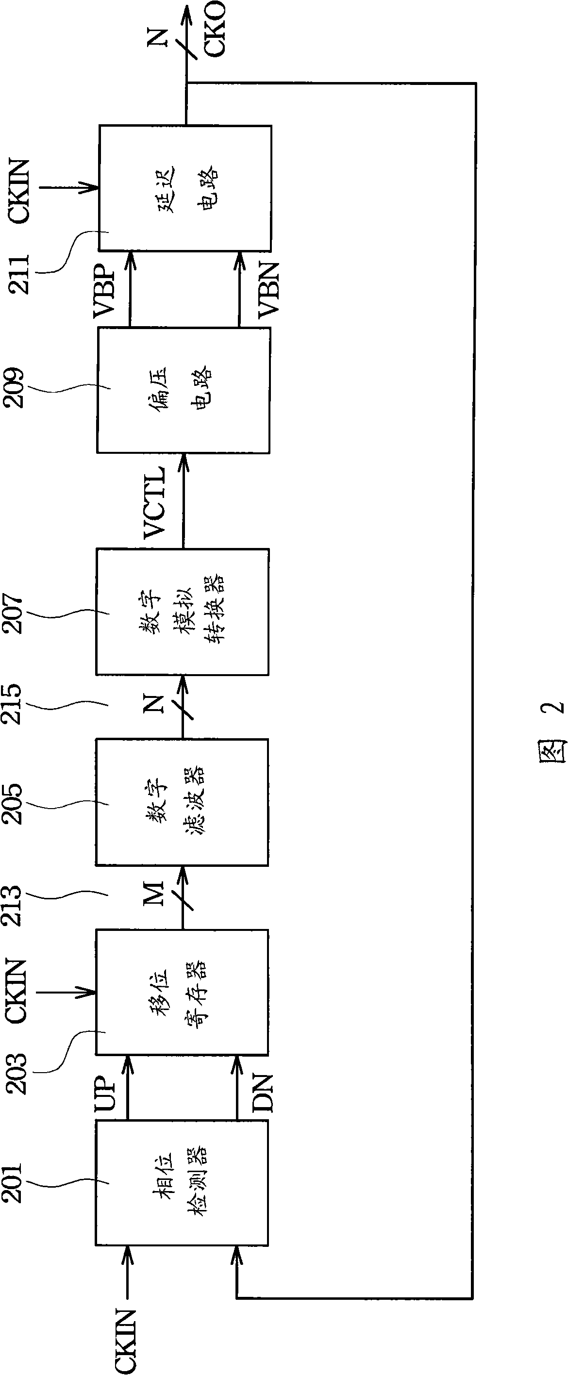
[0032] Please refer to FIG. 2 , which shows a block diagram of a delay-locked loop according to an embodiment of the present invention. The delay locked loop includes a phase detector 201 , a shift register 203 , a digital filter 205 , a digital-to-analog converter 207 , a bias circuit 209 and a delay circuit 211 .

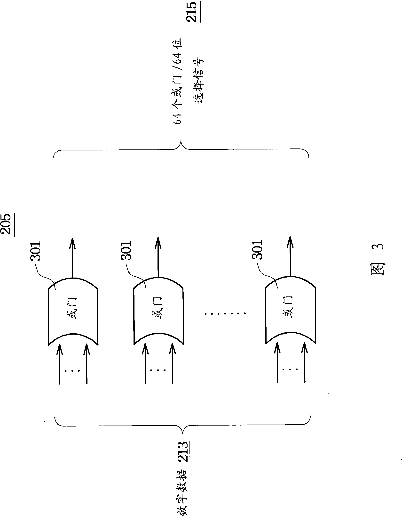
[0033] The phase detector 201 generates a hysteresis signal UP and a leading signal DN according to the phase difference between the input clock signal CKIN and the feedback clock signal CKO. The shift register 203 generates digital data 213 according to the hysteresis signal UP and the leading signal DN, wherein only one bit in the digital elements of the digital data 213 is logic 1 (logic 1). The digital filter 205 generates an N-bit selection signal 215 according to the M-bit digital data 213 , wherein the number of bits M of the digital data 213 is an integer multiple of the number of bits N of the selection signal 215 .

[0034] The digital-to-analog convert...


PUM


Abstract

A delay-locked loop includes a phase detector, a shift register, a digital low pass filter, a digital to analog converter, a bias circuit, and a delay circuit. The phase detector generates a lagging signal and a leading signal corresponding to a phase difference between an input clock signal and a feedback clock signal. The shift register outputs a digital data according to the lagging signal and the leading signal. The digital low pass filter generates a selecting signal according to the digital data. The bias circuit generates a first control voltage and a second control voltage in response to the bias voltage converted from the selecting signal. The delay circuit generates the feedback clock signal corresponding to the first control voltage and the second control voltage.

Description

technical field [0001] The present invention relates to a delay-locked loop, in particular to a delay-locked loop including a digital circuit. Background technique [0002] With the advancement of semiconductor technology, the operating frequency of VLSI circuits has increased significantly. Therefore, electronic equipment needs to upgrade its operating frequency to keep up with the ever-advancing semiconductor process. For example, ultra-high-speed system circuits, such as wireless handsets, fiber optic links, microprocessors, and system-on-chips (SoCs), have all reached GHz levels. [0003] Since many circuits need to be integrated into one chip, the clock signal needs to be widely distributed throughout the chip, which will cause clock skew. For example, when an input clock signal drives the chip, due to the different lengths of the paths passed by the internal clock signal of the chip, there will be an uncertain gap between the input clock signal and the internal clock...

Claims


Application Information

Patent Timeline
Patent Type & Authority Applications(China)
IPC IPC(8): H03L7/06H03L7/085H03L7/093
CPCH03L7/089H03L7/0812
Inventor 黄志豪
Owner HIMAX TECH LTD
Features
  • R&D
  • Intellectual Property
  • Life Sciences
  • Materials
  • Tech Scout
  • Unparalleled Data Quality
  • Higher Quality Content
  • 60% Fewer Hallucinations
Learn More