Fixed-weight loading equipment

A loading device and fixed weight technology, applied in the direction of measuring device, loading/unloading, conveyor control device, etc., can solve the problems of increasing the wear and running resistance of the bearing plate, low measurement accuracy, large drift, etc., and improve the weighing accuracy. , The effect of safe and reliable operation and simple overall structure

Inactive Publication Date: 2009-08-05
孟凡英
View PDF8 Cites 20 Cited by
  • Summary
  • Abstract
  • Description
  • Claims
  • Application Information

AI Technical Summary

Problems solved by technology

The overall performance of this fixed-weight loading method is reliable and basically meets the needs of coal mine production, but there are still the following disadvantages: (1) When the load plate is turned upward from the tail wheel, it is easy to be stuck by the block of water and coal injection, and cannot be attached. After the design is improved, the phenomenon of coal inclusion cannot be completely avoided, which increases the wear and running resistance of the bearing plate, increases the driving power, and increases the amount of maintenance
(2) The rollers on both sides of the bearing plate are often in the state of water seeping from the upper material, resulting in frequent damage to the bearings in the rollers, and serious wear of the rollers, which increases the driving power, requires a large amount of maintenance, and is expensive
The disadvantage is that when the material contains large hard materials, the belt is easily damaged, especially when encountering sharp debris, the belt is easily pierced and torn
[0005] The common disadvantage of the above two types of fixed-weight loading equipment for conveyors is that the weighing part does not avoid the warehouse pressure, and the change of the warehouse pressure directly affects the weighing accuracy, so the error is relatively high
The sensors used are all piezomagnetic sensors or SY-2 electric sensor hydraulic weighing devices, because the sensitive elements of piezomagnetic sensors are made of ferromagnetic materials, which convert the force (such as elastic stress, residual stress) The change is converted into a change in magnetic permeability, which in turn causes a change in the impedance or electromotive force of the coil wound on it, thereby inducing an electrical signal, and then calculating the total amount based on the electrical signal. The disadvantage is that it is not resistant to harsh environments and has a large drift
The working principle of the SY-2 electric sensor hydraulic weighing device is: put the weight to be measured on the piston, the piston moves down, the liquid pressure rises, and the pressure measured by the pressure sensor is converted into the weight of the object. The disadvantage is that the piston is used Sealed, there is oil leakage, after a period of use, the piston moves down, and oil needs to be replenished
Moreover, due to the unstable friction between the seal and the cylinder wall, the pressure measurement is inaccurate, the measurement result is unstable, and the measurement accuracy is low
In addition, the piston is both a seal and a guide, and is very sensitive to installation deviations, which increases the difficulty of installation
In short, the shortcomings of the above two quantitative conveyors limit their popularization and application, so imported equipment occupies the main market among similar equipment

Method used


Image

  • Fixed-weight loading equipment
  • Fixed-weight loading equipment
  • Fixed-weight loading equipment

Examples


Embodiment 1

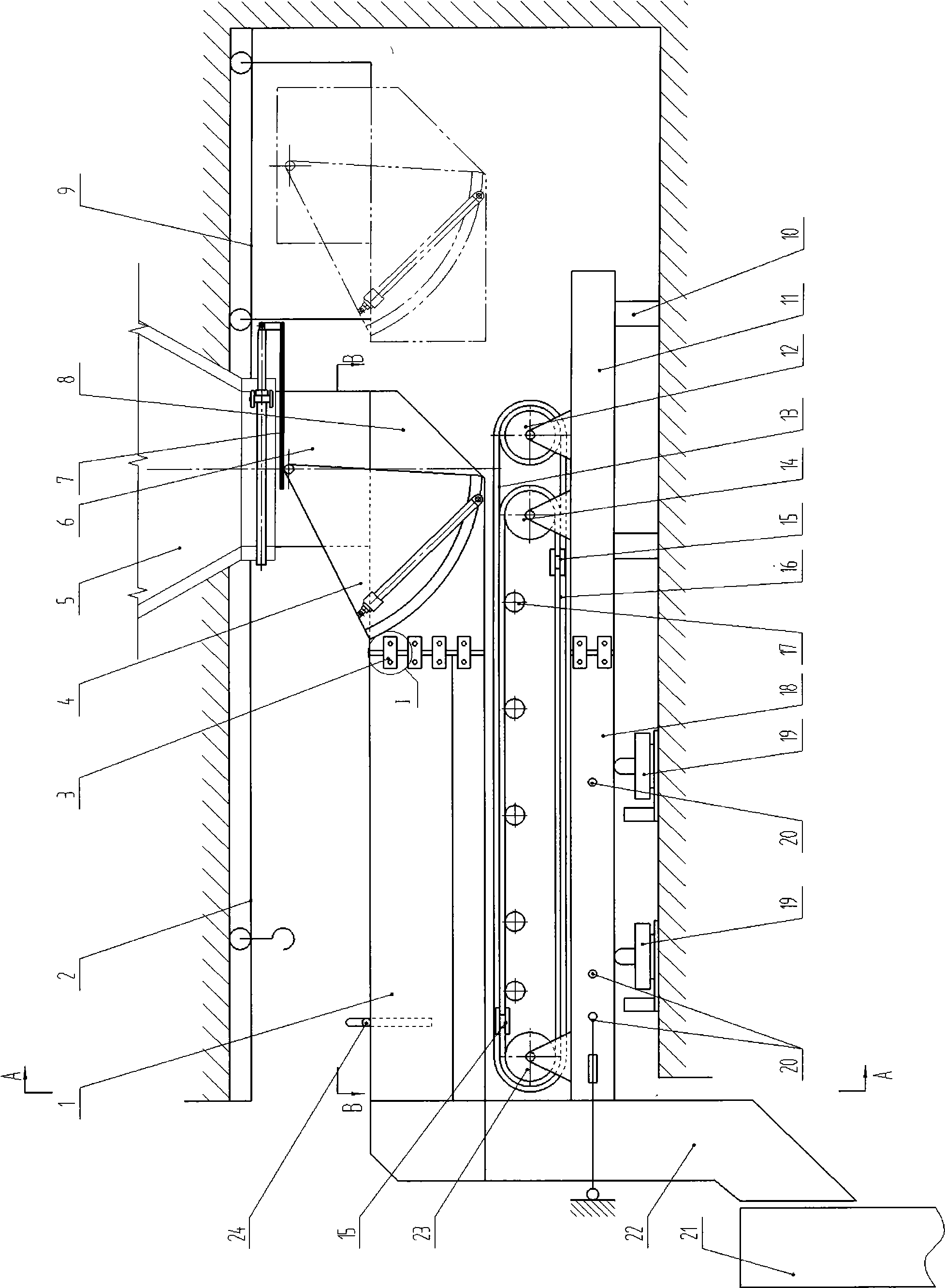
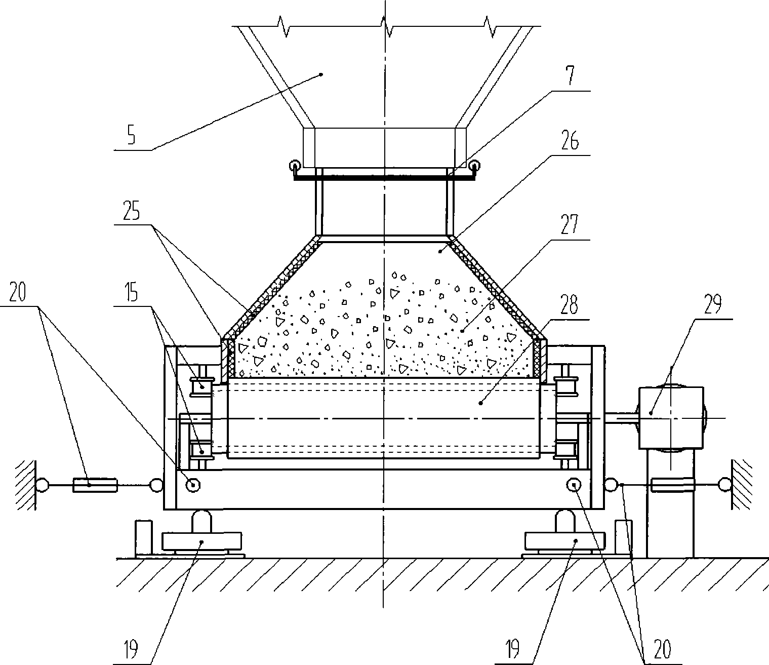
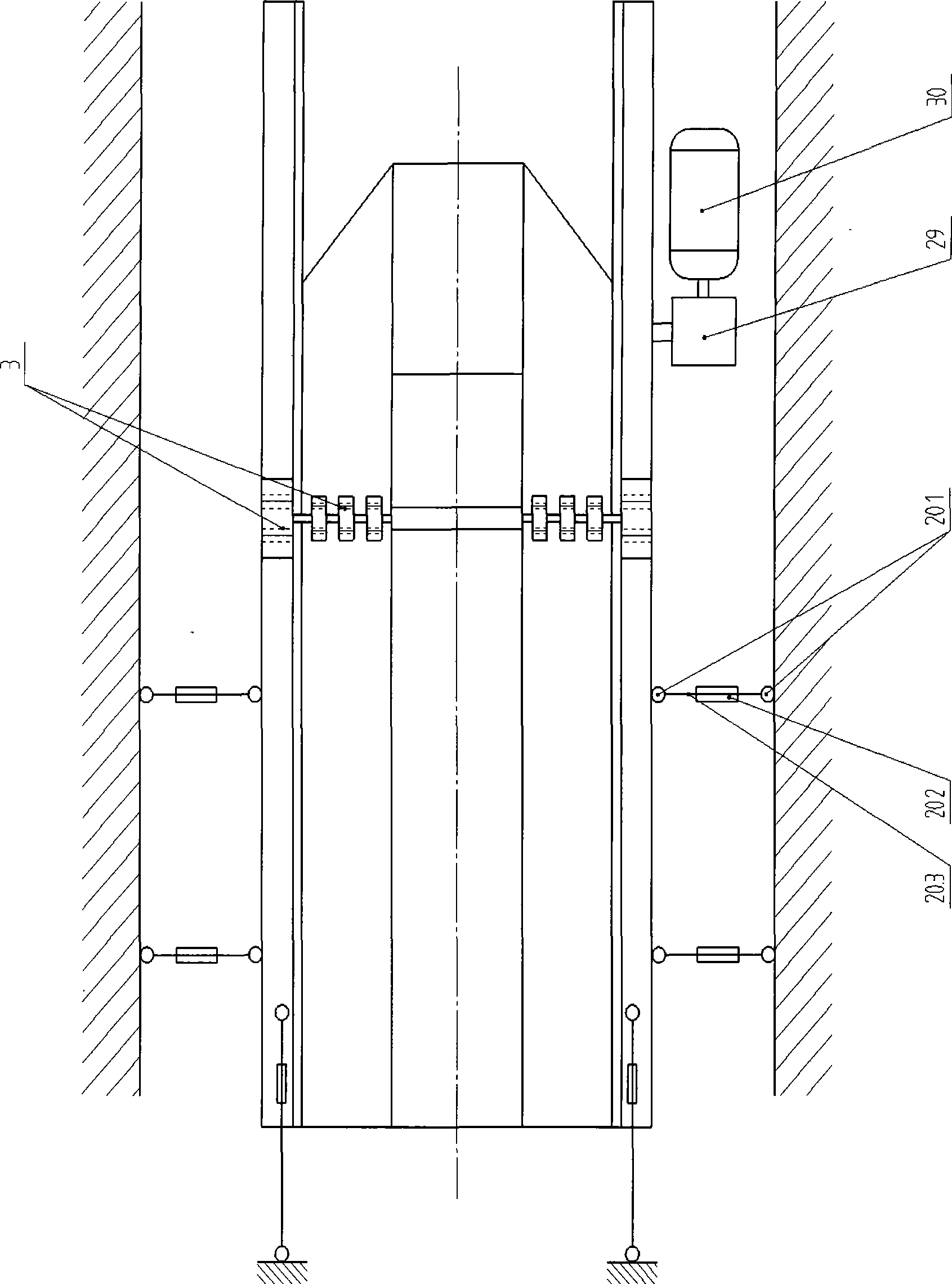
[0039] Such as figure 1 , figure 2 , image 3 , Figure 6 , Figure 7 As shown, the receiving part support 11 is fixed on the foundation by the legs 10, the weighing part support 18 is provided with a weighing sensor 19, and the weighing part support 18 and the receiving part support 11 are provided with a conveying device 28 and a conveying device 28 It consists of a driving roller 14, a redirecting roller 23, a tension roller 12, a belt 13 and a tape 16. The belt 16 is wrapped around the driving roller 14 and the redirecting roller 23. The belt 13 is wrapped on the outside of the tape 16, and is wrapped around the tensioning roller. On the roller 12 and the redirecting roller 23, a number of groups of idlers 17 are arranged between the driving roller 14 and the redirecting roller 23. Above the conveying device 28, a weighing part guide groove 1 and a receiving part guide groove 8 are provided, between the weighing part bracket 18 and the receiving part bracket 11, and the weigh...

Embodiment 2

[0047] Same as Embodiment 1, the difference is that the conveying device 28 is composed of the driving roller 14, the redirecting roller 23 and the adhesive tape 16. The adhesive tape 16 surrounds the driving roller 14 and the redirecting roller 23, eliminating the armor belt 13 and the tension roller. 12, such as figure 2 , image 3 , Figure 4 , Figure 6 , Figure 7 Shown.

Embodiment 3

[0049] Same as embodiment 2, the difference is that the conveying device 28 is composed of the driving roller 14, the redirecting roller 23 and the armor belt 13. The armor belt 13 surrounds the driving roller 14 and the redirecting roller 23, eliminating the tape 16 and tensioning. The roller 12 and the anti-deflection wheel 15 are only installed on both sides of the lower section of the armor belt 13 near the roller approach point, such as image 3 , Figure 5 , Figure 6 , Figure 7 Shown.


PUM


Abstract

The invention relates to a fixed weight loading device for bulk materials, and belongs to the field of mine transportation equipment. The fixed weight loading device for the bulk materials comprises a drive unit, a material guide groove, a conveying device and a support, wherein the material guide groove is arranged on the conveying device which is connected with the support. The fixed weight loading device for the bulk materials is characterized in that the support and the material guide groove are divided into a material receiving part and a weighing part; a weighing sensor is arranged under the weighing part, namely the support; a conveyer belt of the conveying device can be an adhesive tape, a shell belt or a composite adhesive tape and shell belt; the material receiving part and the weighing part, namely the support and the material guide groove are in flexible connection of which the displacement in the vertical direction is not limited; the weighing part, namely the support, is provided with a tensioning device for limiting the displacement in the horizontal direction; and side-slipping resistant wheels are arranged on both sides of the adhesive tape or the shell belt close to a directive point of a roller. The fixed weight loading device for the bulk materials combines a shell belt feeder and force sensor technology, and has the advantages of high weight measuring precision, small mounting space, strong universality, small operating power, reliable use, convenient maintenance, low operating cost and strong environmental adaptation ability.

Description

Technical field [0001] The invention relates to a fixed-weight loading device for bulk materials and belongs to the technical field of mining transportation equipment. Background technique [0002] At present, there are two main ways of loading materials with fixed weight in mine shafts: fixed-weight loading in measuring warehouse and fixed-weight loading by measuring conveyor. [0003] The fixed-weight loading of the metering bin is a more mature and currently the most widely used method of fixed-weight loading. The principle of fixed-weight loading of the weighing bin is to set up one or more quantitative hoppers, one or more weighing sensors are placed under the quantitative hoppers, and after the materials are put into the quantitative hoppers for weighing, the gates are opened, and the materials are transported by their own weight into the transfer equipment . Its advantage is accurate measurement, but in order to make the material flow unimpeded, the dosing bucket is slende...

Claims


Application Information

Patent Timeline
Patent Type & Authority Applications(China)
IPC IPC(8): B65G67/08B65G67/06B65G65/42B65G15/30B65G43/08B65G21/22E21F13/00G01G11/00
Inventor 杜建国董甲前张会远孟凡英
Owner 孟凡英
Why Eureka
Try Eureka