Oil film supporting servo hydraulic cylinder
A servo hydraulic cylinder and oil film technology, applied in the field of servo hydraulic cylinders, can solve the problems of restricting dynamic response characteristics, poor dynamic response characteristics, unsuitable for high-speed operation, etc., and achieve the effect of improving dynamic response, good dynamic response and low friction.
- Summary
- Abstract
- Description
- Claims
- Application Information
AI Technical Summary
Problems solved by technology
Method used
Image

Examples
Embodiment 1
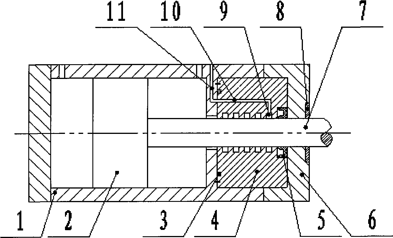
[0014] The utility model relates to a hydraulic cylinder supported by an oil film. The servo hydraulic cylinder as figure 1 Shown: including cylinder 1, piston 2, piston rod 7, guide sleeve 4 and gland 6. The guide sleeve 4 passes through the piston rod 7 and is fixedly installed on the shoulder of the cylinder body 1. A sealing ring 3 is installed at the contact between the left side of the guide sleeve 4 and the shoulder of the cylinder body 1. The guide sleeve 4 and the piston rod 7 There are 3 to 5 balance grooves 9 at the contact point, and the rightmost balance groove 9 communicates with the second oil-repellent passage 11 through the first oil-repellent passage 10; At the end of the cavity, a U-shaped sealing ring 5 is arranged on the right side of the guide sleeve 4 and at the contact with the piston rod 7 .
[0015] Among them: the material of the guide sleeve 4 is bronze; the contact between the guide sleeve 4 and the shoulder of the cylinder body 1 is provided wit...
Embodiment 2
[0017] The utility model relates to a hydraulic cylinder supported by an oil film. The structure of the servo hydraulic cylinder is as follows figure 1 As shown, there are 5-7 balance grooves 9 at the contact point between the guide sleeve 4 and the piston rod 7, and the gap between the guide sleeve 4 and the piston rod 7 is 15-25um; the groove width of the balance groove 9 is 0.8-1, The groove depth is 0.8-1 mm, and the distance between each balancing groove 9 is 5-8 mm.
[0018] All the other are with embodiment 1.
[0019] This embodiment has the following characteristics:
[0020] 1. There are 3 to 7 balance grooves 9 in the inner circle of the guide sleeve 4, and a layer of oil film is formed in the matching gap. The oil in the balance groove 9 not only acts on the piston rod 7 radially, so that it coincides with the center of the guide sleeve 4 , and is conducive to the movement of the piston rod 7 and the piston 2, improving the dynamic response.
[0021] 2. With oi...
PUM
 Abstract
Description
Claims
Application Information
 - R&D
- Intellectual Property
- Life Sciences
- Materials
- Tech Scout
- Unparalleled Data Quality
- Higher Quality Content
- 60% Fewer Hallucinations
Browse by: Latest US Patents, China's latest patents, Technical Efficacy Thesaurus, Application Domain, Technology Topic, Popular Technical Reports.
© 2025 PatSnap. All rights reserved.Legal|Privacy policy|Modern Slavery Act Transparency Statement|Sitemap|About US| Contact US: help@patsnap.com