
Coaxial pulse voltage test device

A technology of pulse voltage and test device, applied in the direction of measurement device, measurement of electrical variables, measurement using digital measurement technology, etc., can solve problems such as nonlinear distortion, inability to obtain test results, etc., and achieve the effect of intuitive observation

Inactive Publication Date: 2009-08-05
CHINA SHIP DEV & DESIGN CENT
View PDF0 Cites 9 Cited by
  • Summary
  • Abstract
  • Description
  • Claims
  • Application Information

AI Technical Summary

Problems solved by technology

The frequency spectrum of electromagnetic pulse is very wide, and its high-end frequency usually reaches hundreds of MHz or even several GHz, and it has high voltage and energy. If it is tested with a current caliper, nonlinear distortion will appear, and accurate testing cannot be obtained. result

Method used


Image

  • Coaxial pulse voltage test device
  • Coaxial pulse voltage test device
  • Coaxial pulse voltage test device

Examples


Embodiment Construction

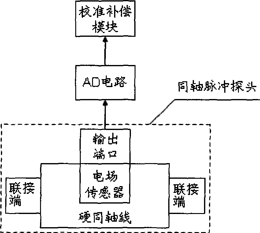
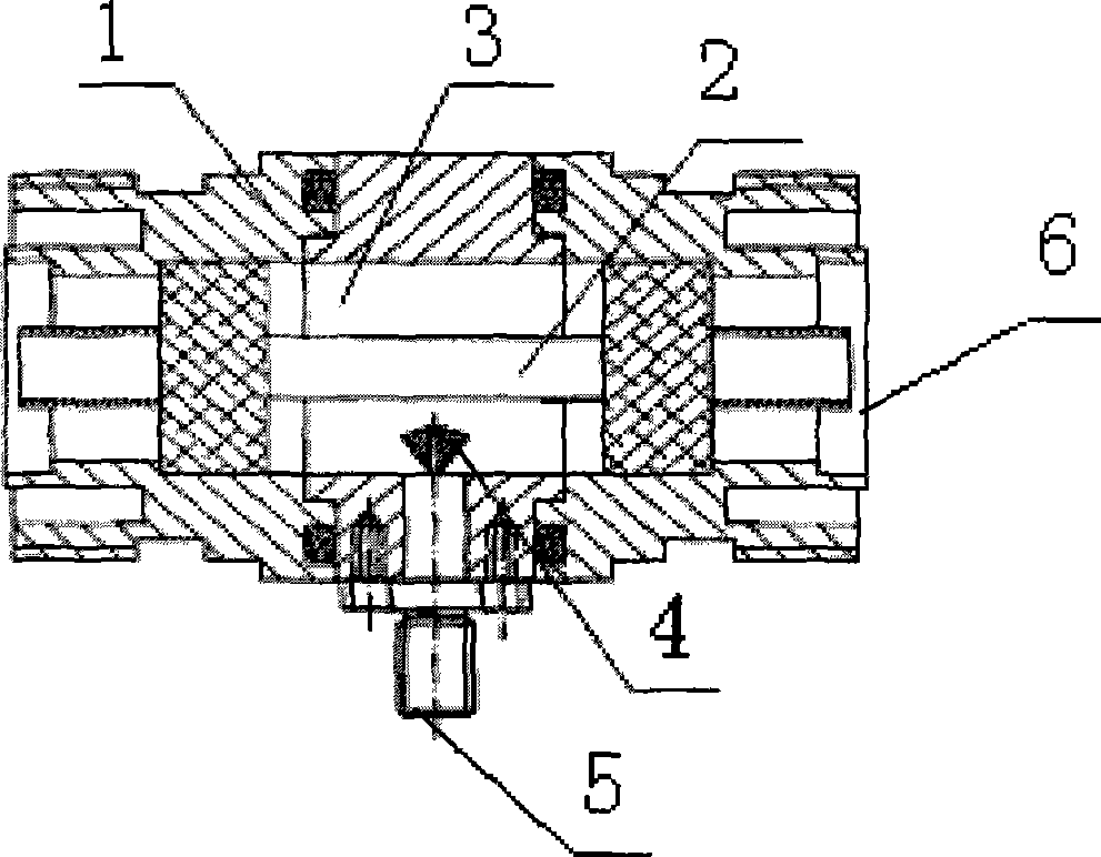
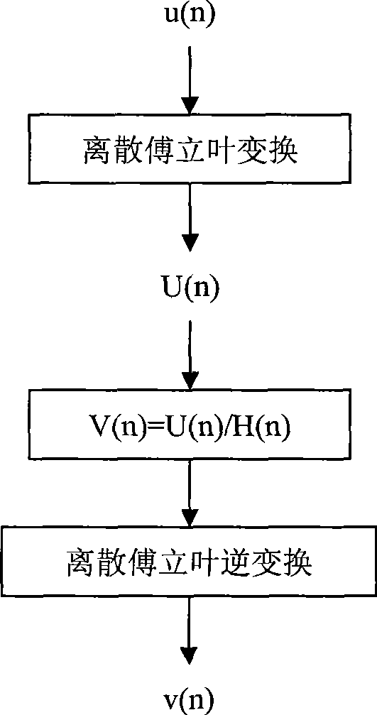
[0035] figure 1 is a structural schematic diagram of an embodiment of the present invention, figure 2 yes figure 1 The structure diagram of the coaxial pulse probe, image 3 It is a flowchart of the calibration compensation module in an embodiment of the present invention. The coaxial pulse voltage testing device comprises: a coaxial pulse probe, whose two connecting ends are respectively connected to two ends of the circuit to be tested to obtain a voltage waveform containing the tested electromagnetic pulse information; an AD circuit, connected to the output of the coaxial pulse probe Connected to the terminal to convert the voltage waveform output by the coaxial pulse probe into a digital signal; the calibration compensation module is connected to the output terminal of the AD circuit to process the converted digital signal and restore the original pulse waveform.

[0036] The coaxial pulse probe includes a joint-shaped hard coaxial line and an electric field sensor. Th...


PUM


Abstract

The invention discloses a coaxial pulse voltage testing device which comprises a coaxial pulse probe, an AD circuit and a calibrating compensation module. Two connecting ends of the coaxial pulse probe are respectively connected to two ends of a tested circuit to obtain voltage waveform containing tested electromagnetic pulse information; the AD circuit is connected with the output end of the coaxial pulse probe and converts the voltage waveform output by the coaxial pulse probe into a digital signal; and the calibrating compensation module is connected with the output end of the AD circuit, processes the converted digital signal and reverts an original pulse waveform. The coaxial pulse voltage testing device is suitable for a very wide electromagnetic pulse frequency spectrum, can accurately test the electromagnetic pulse voltage signal of an ns-grade ascending edge, and has very high voltage withstanding property.

Description

technical field [0001] The invention relates to a device for testing the coupled electromagnetic pulse voltage on the coaxial cable, that is, a coaxial pulse voltage testing device. Background technique [0002] The device used to test the coupling voltage on the coaxial cable is called a current probe, and the common current probe on the market is called a current caliper. The current caliper adopts the principle of transformer. The wire passing the current is the primary of the transformer, and the current probe is the secondary of the transformer. There is a certain mutual inductance between the primary and secondary. There is a magnetic core in the structure of the current caliper. When the test frequency enters the microwave band, the magnetic core material will appear magnetic saturation under strong current and high frequency, which will cause nonlinear distortion of the measurement results. Therefore, the high-frequency performance of the current caliper is not idea...

Claims


Application Information

Patent Timeline
IPC IPC(8): G01R19/25G01R15/00
Inventor 谭辉陈久春黄明亮易学勤邢芳
Owner CHINA SHIP DEV & DESIGN CENT
Learn More