Contra-positioned bipolar battery

A bipolar battery, bipolar plate technology, applied in the direction of flat battery, secondary battery manufacturing, primary battery to battery grouping, etc., can solve the problem of reduced power density and energy density of bipolar plate, inconvenient for large-capacity single battery Application, insufficient electrochemical reaction and other problems, to achieve the effect of uniform current density, improved high temperature environmental adaptability, and high current charge and discharge capacity

Inactive Publication Date: 2009-08-05
SHANGHAI JIAO TONG UNIV
View PDF1 Cites 6 Cited by
  • Summary
  • Abstract
  • Description
  • Claims
  • Application Information

AI Technical Summary

Problems solved by technology

Its disadvantages are: it is a "sandwich" structure, and the sealing between each single battery is difficult; one side of the bipolar plate is the positive electrode, and the other side is the negative electrode, and each single battery can only be composed of one positive electrode and one negative electrode. , which is not convenient for application in large-capacity single batteries; only one side of the positive and negative plates on both sides of the bipolar plate undergoes a complete electrochemical reaction, and the active material on the other side is not fully utilized, and the electrochemical reaction is insufficient, resulting in The capacity of the electrodes is low; except for the positive and negative unipolar electrodes at both ends of the module, the middle is a bipolar electrode, and the positive and negative electrodes in the middle need to add a conductive metal substrate, compared with the conventional unipolar , the power density and energy density of the bipolar plate are reduced

Method used


Image

  • Contra-positioned bipolar battery
  • Contra-positioned bipolar battery
  • Contra-positioned bipolar battery

Examples


Embodiment Construction

[0035] The embodiments of the present invention are described in detail below in conjunction with the accompanying drawings: this embodiment is implemented under the premise of the technical solution of the present invention, and detailed implementation methods and processes are provided, but the protection scope of the present invention is not limited to the following implementations example.

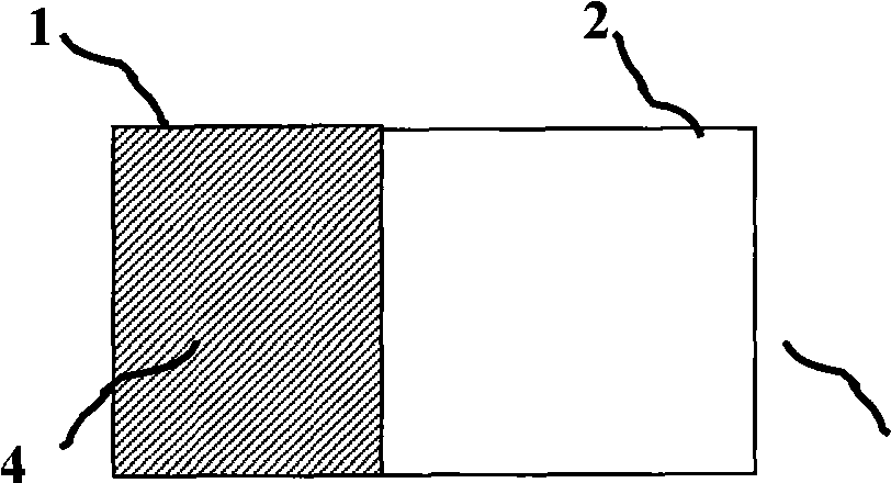
[0036] Such as figure 1 As shown, the opposite bipolar plate conductor 3 of the present embodiment is a kind of opposite bipolar plate conductor, and the material required by one of the positive pole conductor or the negative pole conductor is used as the basic conductive material to form the opposite bipolar conductor. The conductive substrate of the pole plate, one end of the conductive substrate is the corresponding pole piece conductor 1, and the other end of the conductive substrate is formed by electroplating or other methods to wrap the pole piece conductor that is different fro...


PUM


Abstract

The invention relates to the technical field of batteries, in particular to an opposite bipolar plate and an opposite bipolar battery. The opposite bipolar plate is mainly characterized in that one end of a conductive substrate is provided with an anode plate, and the other end thereof is provided with a cathode plate. The opposite bipolar battery is mainly characterized in that the two ends thereof are respectively provided with a unipolar anode plate group and a unipolar cathode plate group; the opposite bipolar plate groups with the bipolarity are stacked in sequence between the unipolar anode plate group and the unipolar cathode plate group; the adjacent single batteries are internally connected in series as the opposite bipolar plate penetrates the separator; no single battery requires external connecting component; the structure is simple; the current density, working conditions and environmental conditions of heat and moisture for the polar plates are uniform; the internal resistance and the connection requirements are greatly reduced; the weight is greatly reduced; the reliability and security are substantially improved; the service life is long; and the cost is greatly reduced. The invention can greatly improve the power density and energy density of the battery, and simultaneously improves the high-current battery charge and discharge capacity, the charge-discharge efficiency, the adaptability to the thermal environment, the anti-vibration capability and the like.

Description

technical field [0001] The invention relates to a bipolar battery in the field of battery technology, in particular to an opposed bipolar battery. Background technique [0002] The voltage of commonly used battery cells is generally low. For example, the voltage of a lithium-ion cell is 3.6V, the voltage of a lead-acid cell is 2.0V, and the voltage of a nickel-metal hydride cell and a nickel-cadmium cell is 1.2V. In order to meet the power and energy requirements of the battery system in actual use, multiple single batteries need to be used in series in groups. [0003] Each single battery has a separate sealed shell. In addition to the positive and negative plates, diaphragm, and electrolyte, the square single battery has separate positive and negative tabs, positive and negative current collectors, and positive and negative anti-rotation devices. , the proportion of inert substances is large, the positive and negative plates must be welded with the tabs, and the tabs must...

Claims


Application Information

Patent Timeline
Patent Type & Authority Applications(China)
IPC IPC(8): H01M4/02H01M10/04H01M6/48
CPCY02E60/12Y02E60/10Y02P70/50
Inventor 杨林羌嘉曦陈自强敖国强秦俊
Owner SHANGHAI JIAO TONG UNIV
Why Eureka
Try Eureka