Microcomputer controlled standby electric power automatic throwing method with inner bridge wire enlarged

A backup power supply, automatic input technology, applied in emergency power supply arrangements, electrical components, circuit devices, etc., can solve the problem that the operation mode cannot fully cover the expansion of the inner bridge wiring operation mode.

Inactive Publication Date: 2009-08-05
STATE GRID JIANGSU ELECTRIC POWER CO ZHENJIANG POWER SUPPLY CO
View PDF1 Cites 20 Cited by
  • Summary
  • Abstract
  • Description
  • Claims
  • Application Information

AI Technical Summary

Problems solved by technology

As for the backup automatic switch-on device whose primary main wiring is to expand the inner bridge connection, although there are also manufacturers of standby automatic switch-on devices, the control method and basic principle of the automatic switch-on of the backup power supply are based on the pre-set operation. method, that is, "exhaustive method", and set the process in this operation mode to complete, the operation mode does not fully cover all the operation modes of the expanded inner bridge line
[0003] For ordinary inner bridge wiring, the Chinese patent application with the publication number CN1445906 has recorded a method for the automatic input of a microcomputer-controlled backup power supply of the inner bridge wiring, which can be better applied to its standby self-injection device, and can cover common All operating modes of the inner bridge line, but there is no ideal standby automatic switching control method for expanding the inner bridge line

Method used


Image

  • Microcomputer controlled standby electric power automatic throwing method with inner bridge wire enlarged
  • Microcomputer controlled standby electric power automatic throwing method with inner bridge wire enlarged
  • Microcomputer controlled standby electric power automatic throwing method with inner bridge wire enlarged

Examples


Embodiment Construction

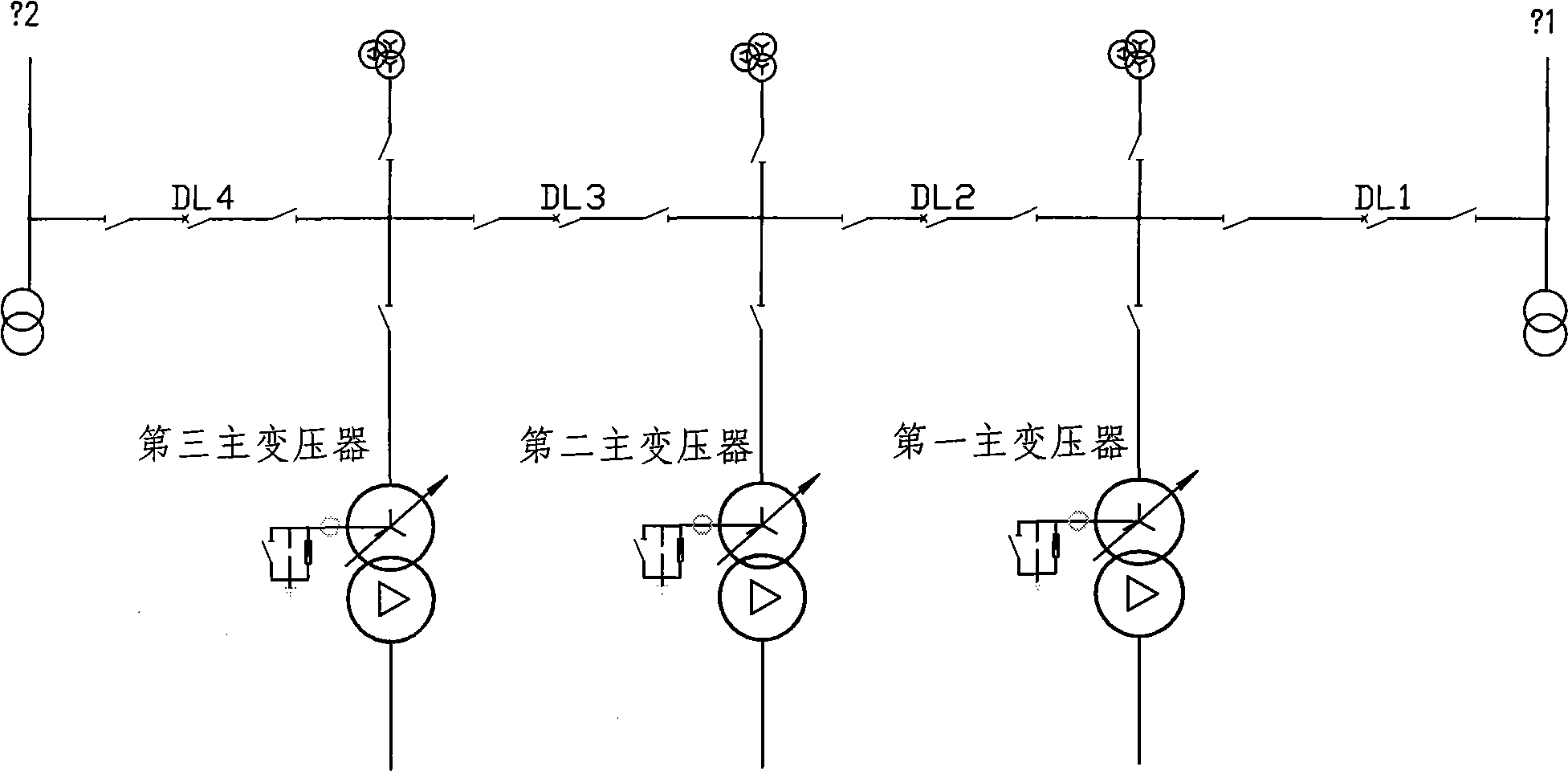
[0040] Such as figure 1As shown, the primary main wiring of the substation in the power transmission and distribution network to which the method of the present invention is applied is a standard double-power-supplied enlarged internal bridge wiring, which includes two power supplies, and the two power supply incoming lines are respectively Circuit breaker DL1 and circuit breaker DL4 are connected, and circuit breaker DL3 and circuit breaker DL4 are connected between the two power supply lines as bridge circuit breakers; three main transformers are connected in sequence between each circuit breaker, namely: the first main transformer The transformer, the second main transformer and the third main transformer; the line side of the power supply incoming line and the high voltage side or low voltage side of the transformer are all connected with voltage transformers. That is, two power supply lines, three step-down main transformers, and four circuit breakers.

[0041] Taking t...


PUM


Abstract

The invention belongs to the control technology of the electric network for power transmission and distribution and relates to a method for the automatic use of the micro-computer controlled standby power supply of an expanded inter-bridge connection. The applied expanded inter-bridge connection comprises two power supplies; the inlet wires of the two power supplies are respectively connected with a circuit breaker DL1 and a circuit breaker DL4; a circuit breaker DL3 and the circuit breaker DL4 are connected between the inlet wires of the two power supplies so as to be taken as a bridge circuit breaker; the circuit breaker DL1, the circuit breaker DL2 and the circuit breaker DL4 are taken as three circuit breakers in a normal inter-bridge connection; the method for the automatic use of the micro-computer controlled standby power supply is used for controlling the three circuit breakers; simultaneously, the circuit breaker DL1, the circuit breaker DL3 and the circuit breaker DL4 are also taken as three circuit breakers in a normal inter-bridge connection; the method for the automatic use of the micro-computer controlled standby power supply is also used for controlling the three circuit breakers; furthermore, the two control processes are carried out at the same time. The method has simple action principle and high reliability and completely meets the basic principle of the automatic use of the standby power supply.

Description

technical field [0001] The invention belongs to the control technology of electric power transmission and distribution network, and relates to a microcomputer-controlled backup power supply automatic input method for expanding inner bridge wiring. Background technique [0002] At present, the backup power automatic switch-on device (referred to as standby automatic switch-on device) operated by substations is commonly used in which the primary main wiring of the substation is an inner bridge connection, a single-bus segment connection and a single-bus connection. As for the backup automatic switch-on device whose primary main wiring is to expand the inner bridge connection, although there are also manufacturers of standby automatic switch-on devices, the control method and basic principle of the automatic switch-on of the backup power supply are based on the pre-set operation. method, that is, "exhaustive method", and set the process in this operation mode to complete, the o...

Claims


Application Information

Patent Timeline
Patent Type & Authority Applications(China)
IPC IPC(8): H02J9/06
Inventor 汤大海
Owner STATE GRID JIANGSU ELECTRIC POWER CO ZHENJIANG POWER SUPPLY CO
Why Eureka
Try Eureka