Supercharge Your Innovation With Domain-Expert AI Agents!

Oscillating circuit

An oscillating circuit and circuit technology, applied in the direction of electrical components, automatic power control, etc., can solve problems such as unusable performance and inability to provide multiple phases, and achieve the effects of low supply voltage, less redesign time, and reduced design complexity.

Inactive Publication Date: 2009-08-05
IND TECH RES INST
View PDF0 Cites 2 Cited by
  • Summary
  • Abstract
  • Description
  • Claims
  • Application Information

AI Technical Summary

Problems solved by technology

However, the performance is limited to digitally controlled oscillator circuits and cannot be used in related high-speed transmission systems. As far as the current literature on digitally controlled oscillator circuits is concerned, the oscillation cycle is about tens of logic gates in transmission delay, which can produce the smallest time resolution. Around the propagation delay of 0.1 logic gate
In addition, the current digitally controlled oscillator circuit cannot provide multi-phase output. As far as the components provided by the 0.18 micron process are concerned, the frequency resolution is about several ps, and the frequency jitter generated is about hundreds of ps, so it can only be used in the output Low-speed transmission system with a speed of about several MHz to tens of MHz

Method used


Image

  • Oscillating circuit
  • Oscillating circuit
  • Oscillating circuit

Examples


Embodiment Construction

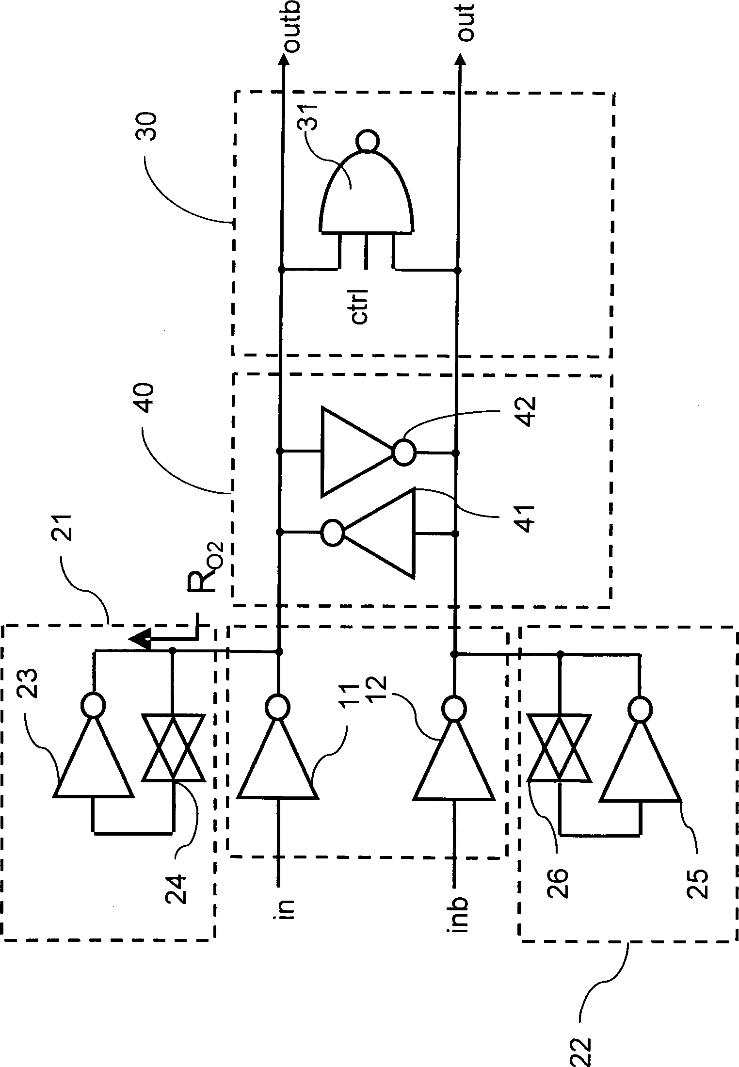
[0055] Please refer to figure 1 , is a schematic diagram of a digitally controlled oscillating circuit disclosed in an embodiment of the present invention. The basic principle of this circuit is to use an inductive load circuit and a capacitive load circuit to generate a resonance phenomenon, and at the same time control the equivalent capacitance of the capacitive load circuit through an external signal value to fine-tune the resonant frequency. The detailed operation and composition are described below.

[0056] The digitally controlled oscillating circuit shown in the figure is composed of a first inductive load circuit 21 , a second inductive load circuit 22 and a capacitive load circuit 30 . The first inductive load circuit 21 and the second inductive load circuit 22 have the characteristic of inductance, and the capacitive load circuit 30 has the characteristic of capacitance. Therefore, an oscillation circuit can be formed by combining the characteristics of inductance...


PUM


Abstract

The invention relates to an oscillation circuit; wherein, a first inverter and a second inverter respectively receives a first signal and a second signal and respectively invert the first signal and the second signal so as to respectively output a first inversion signal and a second inversion signal. The output end of the first inverter is electrically connected with a first inductive load; the output end of the second inverter is electrically connected with a second inductive load; in addition, a capacitive load is respectively and electrically connected with the output end of the first inverter and the output end of the second inverter and respectively receives the first inversion signal and the second inversion signal; wherein, the capacitance value of the capacitive load changes with a control signal. For a digital oscillation circuit of the invention, as the circuit realizes expectation by a digital circuit unit, thus reducing the use of large-scale passive elements such as an inductor, a capacitor and a resistor, simultaneously reducing the large-scale use of active elements such as a current source, further being capable of reducing the area of the circuit and being operated in lower supply voltage.

Description

technical field [0001] The invention relates to a capacitive load element, in particular to a capacitive load element of a signal delay circuit. Background technique [0002] The phase-locked loop is one of the necessary modules of the transmission system, and its main function is to provide the frequency required for system operation. A general PLL includes a frequency phase detector (Frequency Phase Detector), a loop filter circuit (Loop Filter), an oscillator circuit (Oscillator), and a frequency divider (Frequency Divider). According to different circuit implementation methods, it can be divided into analog phase-locked loop and digital phase-locked loop. [0003] In an analog phase-locked loop (Analog PLL), a linear frequency-phase detection circuit compares the frequency error and phase error between the reference frequency and the frequency generated by the loop, and converts these errors into a voltage output. In order to stabilize the system and filter high-freque...

Claims


Application Information

Patent Timeline
IPC IPC(8): H03L7/099
Inventor 吕鸿文苏朝琴
Owner IND TECH RES INST
Features
  • R&D
  • Intellectual Property
  • Life Sciences
  • Materials
  • Tech Scout
  • Unparalleled Data Quality
  • Higher Quality Content
  • 60% Fewer Hallucinations
Learn More