Light modulation control circuit for LED

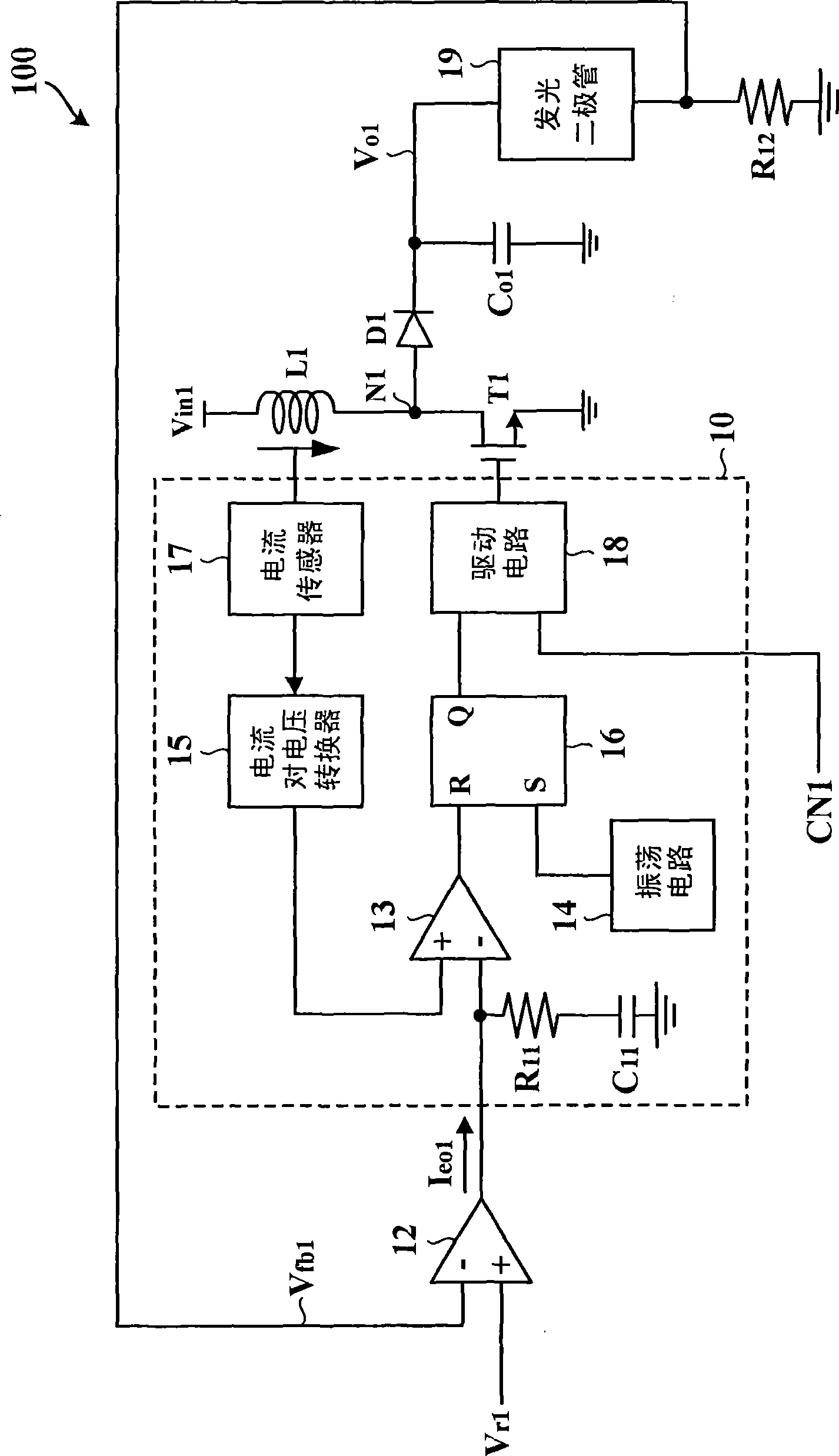
A dimming control circuit and light-emitting diode technology, applied in the direction of electric lamp circuit layout, light source, electric light source, etc., can solve the problem of excessive inrush current of inductor L1

Inactive Publication Date: 2009-08-05
GLOBAL MIXED MODE TECH
View PDF0 Cites 26 Cited by
  • Summary
  • Abstract
  • Description
  • Claims
  • Application Information

AI Technical Summary

Problems solved by technology

And when the dimming control signal CN1 changes from a low potential to a high potential, the in

Method used


Image

  • Light modulation control circuit for LED
  • Light modulation control circuit for LED

Examples


Embodiment Construction

[0007] The foregoing and other objects, features, and advantages of the present invention will be more apparent from the following description and accompanying drawings. Preferred embodiments according to the present invention will now be described in detail with reference to the accompanying drawings.

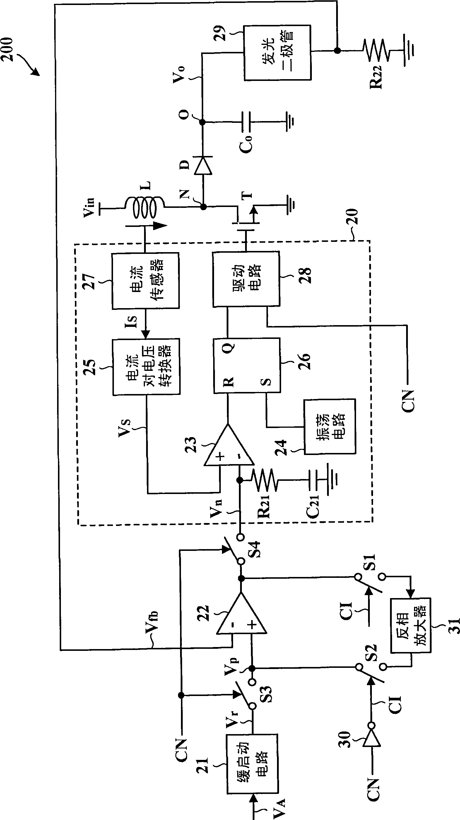
[0008] figure 2 A circuit diagram of an LED dimming control circuit 200 according to the present invention is shown.

[0009] exist figure 2 In the example, the LED dimming control circuit 200 is implemented by a step-up voltage regulator, which is used to convert the input voltage V in converted to the desired output voltage V o , and then drive the light emitting diode 29 . The LED dimming control circuit 200 includes a slow start circuit 21, an error amplifier 22, switches S1 to S4, an inverter 30, an inverting amplifier 31, a switching control circuit 20, an inductor L, a transistor T, a diode D, and a resistor R 22 , and the output capacitor C o , coupled with eac...


PUM


Abstract

The invention provides an LED (light emitting diode) dimming control circuit which is used for driving LEDs. The LED dimming control circuit comprises an inductor, a transistor, a dimming control signal, a feedback signal, a switching control circuit, an error amplifier and an inverting amplifier. The switching control circuit is controlled by the dimming control signal and the feedback signal; the transistor is controlled by the switching control circuit; and the output end and the non-inverting input end of the error amplifier form a negative feedback path through the inverting amplifier.

Description

technical field [0001] The invention relates to a light-emitting diode dimming control circuit, in particular to a light-emitting diode light-adjusting control circuit which can prevent the inrush current of the inductor from being too large and the output voltage from being too high. Background technique [0002] figure 1 A circuit diagram of a conventional LED dimming control circuit 100 is shown. exist figure 1 In the example, the light-emitting diode dimming control circuit 100 is implemented by a boost-type (Boost-Type) voltage regulator, which is used to convert the input voltage V in1 converted to the desired output voltage V o1 , and then drive the light emitting diode 19 . The switching control circuit 10 includes a capacitor C 11 , resistance R 11 , a comparator 13, an oscillation circuit 14, a current-to-voltage converter 15, a latch 16, a current sensor 17, and a drive circuit 18. Resistance R 12 The coupling point between one end of the LED and the catho...

Claims


Application Information

Patent Timeline
IPC IPC(8): H05B37/02
Inventor 张简上裕陈天赐
Owner GLOBAL MIXED MODE TECH
Why Eureka
Try Eureka