
Riveting connector

A connecting piece and riveting technology, applied in the direction of connecting components, thin plate connection, mechanical equipment, etc., can solve the problems of nut falling off, weak axial tensile force, etc., and achieve firm riveting, large axial bearing capacity, large radial Anti-torsion effect

Inactive Publication Date: 2009-08-12
ZTE CORP SHENZHEN CITY
View PDF0 Cites 8 Cited by
  • Summary
  • Abstract
  • Description
  • Claims
  • Application Information

AI Technical Summary

Problems solved by technology

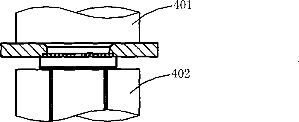
[0002] At present, the commonly used riveted fasteners are mostly pressure riveting structures, such as circular pressure riveting nuts, which are placed in pre-punched round holes (the diameter of the round hole and the diameter of the pressure riveting nut are clearance fit). In the metal sheet (the thickness of the sheet is slightly larger than the step height of the rivet nut), because the strength of the rivet nut is greater than the metal sheet, through the extrusion of the upper die and the lower die, the metal sheet is squeezed by the sharp teeth, and the material is squeezed. Press into the conical gap of the nut, so that the nut and the sheet are riveted together, and the sharp teeth of the nut can prevent the nut from rotating; this structure has high radial torsional strength, but the axial tensile force is weak, so screwing It is easy to push the nut out and fall off

Method used


Image

  • Riveting connector
  • Riveting connector
  • Riveting connector

Examples


Embodiment Construction

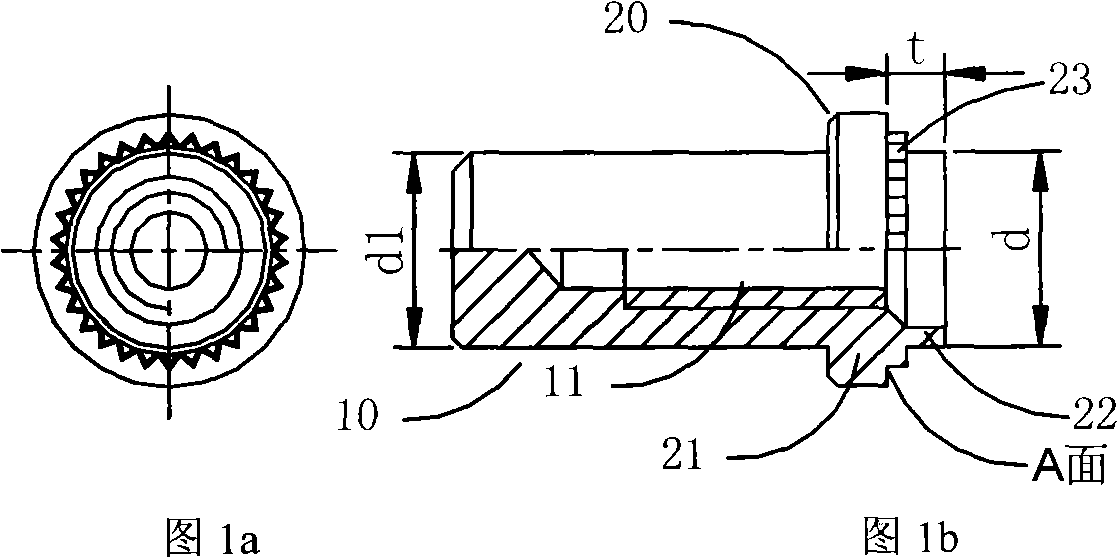
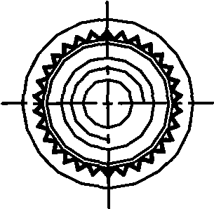
[0018] As shown in Figure 1a, Figure 1b As shown, the present embodiment takes a nut as an example for illustration. The riveted connector includes a connecting part 10 and a riveted part 20. The connecting part 10 is provided with a threaded hole 11 for connecting with other parts. The riveted part 20 is used for For riveting fastening with the plate to be riveted, it is hollow inside, the inner diameter of the blind threaded hole 11 is smaller than the inner diameter of the inner hole of the riveting part 20, and the transition between the blind threaded hole 11 and the inner hole of the riveting part 20 is a conical surface, and the riveting The part 20 includes a base 21 and a deformed riveting column 22. The deformed riveting column 22 is in the shape of a short tube, the height t is greater than the thickness of the sheet to be riveted, and the bottom is provided with ring-shaped distribution tines 23 to prevent rotation. It is in contact with the plate to be riveted, an...


PUM


Abstract

The invention discloses a riveting connecting piece, which comprises a connecting part and a riveting part, wherein a through threaded hole or a blind threaded hole is formed in the riveting connecting piece preferentially, and the inside diameter of the hole is smaller than that of the riveting part; naturally, the hole can be a through hole or a blind hole arranged in the riveting connecting piece so as to adopt other connecting modes; the connecting part is used for connecting other components, and the riveting part is used for riveting and tightening with a sheet material to be riveted; the riveting part is hollow inside and comprises a base part and a deformed riveting column; the deformed riveting column is of a short pipe shape, the bottom thereof is provided with annularly-distributed pointed teeth towards the outside to prevent rotation, one end face of the base part contacts with the sheet material to be riveted, the other end of the base part is connected with the connecting part, and the outside diameter of the pointed teeth is smaller than that of the base part; the material of the riveting connecting piece is a plastic deformation material of which the strength is higher than that of the sheet material to be riveted, and the material is preferably stainless steel, or other metallic materials or nonmetal materials. The riveting connecting piece not only has stronger axial bearing capacity, but also has stronger radial twisting resistance, thus the riveting is firmer.

Description

technical field [0001] The invention relates to a fastening connector, in particular to a riveted connector. Background technique [0002] At present, the commonly used riveted fasteners are mostly pressure riveting structures, such as circular pressure riveting nuts, which are placed in pre-punched round holes (the diameter of the round hole and the diameter of the pressure riveting nut are clearance fit). In the metal sheet (the thickness of the sheet is slightly larger than the step height of the rivet nut), because the strength of the rivet nut is greater than the metal sheet, through the extrusion of the upper die and the lower die, the metal sheet is squeezed by the sharp teeth, and the material is squeezed. Press into the conical gap of the nut, so that the nut and the sheet are riveted together, and the sharp teeth of the nut can prevent the nut from rotating; this structure has high radial torsional strength, but the axial tensile force is weak, so screwing It is e...

Claims


Application Information

Patent Timeline
Patent Type & Authority Applications(China)
IPC IPC(8): F16B17/00F16B5/04
Inventor 谢利红
Owner ZTE CORP SHENZHEN CITY
Learn More