Thermal analysis method for measuring glass transition temperature of amorphous alloy

A glass transition and amorphous alloy technology, applied in the field of amorphous alloy and thermal analysis testing, can solve the problems of single function and narrow application area, and achieve the effect of overcoming data dispersion and great application prospects

Inactive Publication Date: 2009-08-12
GUANGDONG UNIV OF TECH
View PDF0 Cites 16 Cited by
  • Summary
  • Abstract
  • Description
  • Claims
  • Application Information

AI Technical Summary

Problems solved by technology

Thermal and physical property testing instruments such as dilatometers have relative

Method used


Image

  • Thermal analysis method for measuring glass transition temperature of amorphous alloy
  • Thermal analysis method for measuring glass transition temperature of amorphous alloy
  • Thermal analysis method for measuring glass transition temperature of amorphous alloy

Examples


Embodiment 1

[0022] 1. The master alloy was smelted in a non-consumable arc melting furnace, and the Fe-B-Y-Nb bulk amorphous sample was prepared by a water-cooled copper mold suction casting method;

[0023] 2. Use a differential thermal analyzer to measure the heat flow-temperature curve of the sample obtained in step 1 under nitrogen atmosphere, 20°C / min, and DSC mode, see figure 1 the a curve;

[0024] 3. The heat flow-temperature curve obtained in step 2 is derived from the temperature to obtain the heat flow rate-temperature curve, see figure 1 the b-curve;

[0025] 4. On the heat flow rate-temperature curve obtained in step 3, find out the peak corresponding to the glass transition, and determine the onset temperature (T i ) is 600.83℃, the peak temperature (T P ) is 625.09°C, thus determining the reference temperature range [1] as: from the initial temperature of 600.83°C (T i ) to a peak temperature of 625.09°C (T P );

[0026] 5. On the heat flow-temperature curve, within a...

Embodiment 2

[0028] 1. The master alloy was smelted in a non-consumable arc melting furnace, and the Fe-B-Y-Nb bulk amorphous sample was prepared by a water-cooled copper mold suction casting method;

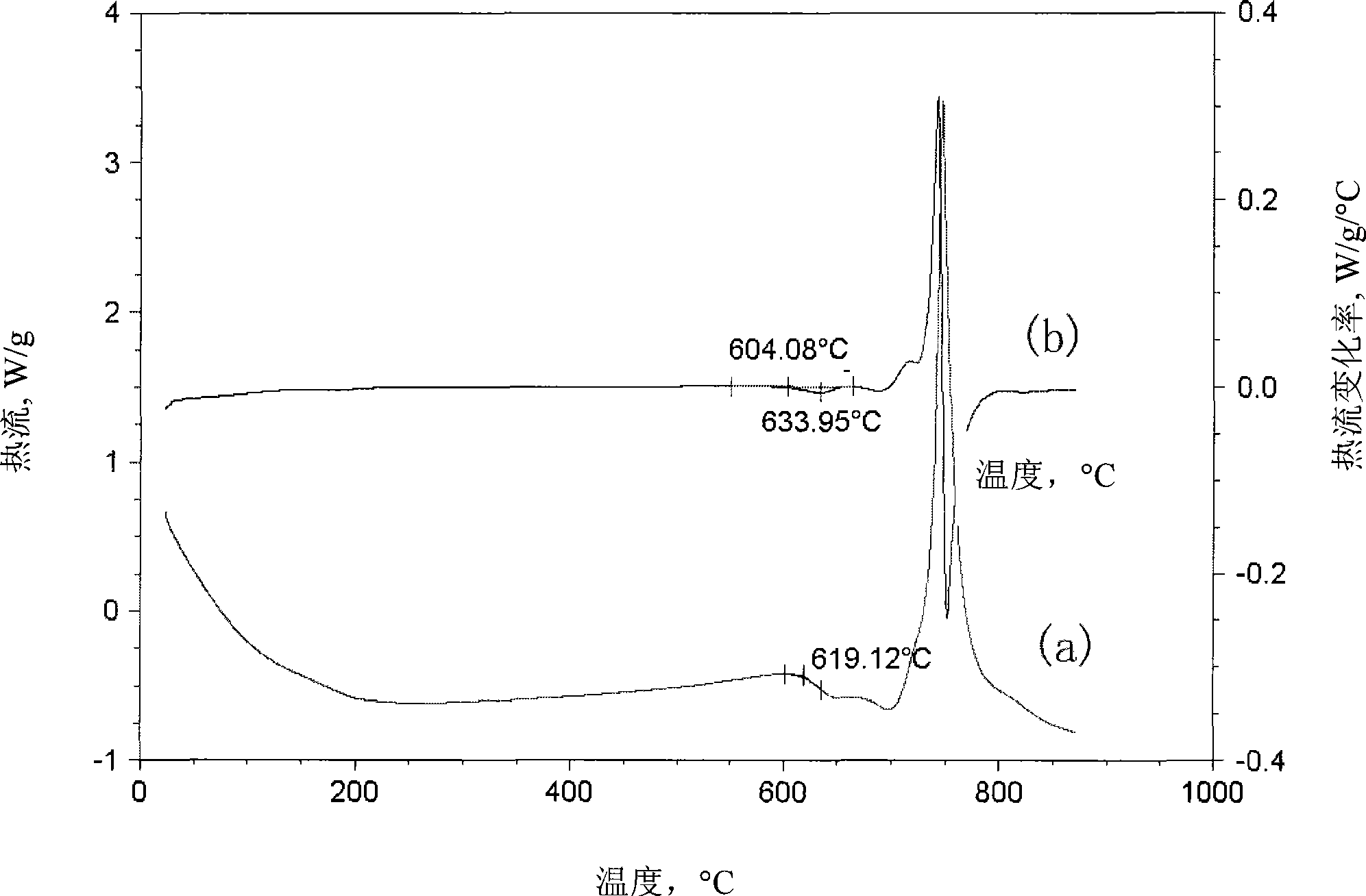
[0029] 2. Use a differential thermal analyzer to measure the heat flow-temperature curve of the sample obtained in step 1 under nitrogen atmosphere, 30°C / min, and DSC mode, see figure 2 the a curve;

[0030] 3. The heat flow-temperature curve obtained in step 2 is derived from the temperature to obtain the heat flow rate-temperature curve, see figure 2 the b-curve;

[0031] 4. On the heat flow rate-temperature curve obtained in step 3, find out the peak corresponding to the glass transition, and determine the onset temperature (T i ) is 604.08℃, the peak temperature (T P ) is 633.95°C, thus determining the reference temperature range [1] as: from the initial temperature of 604.08°C (T i ) to a peak temperature of 633.95°C (T P );

[0032] 5. On the heat flow-temperature curve, within...

Embodiment 3

[0034] 1. The master alloy was smelted in a non-consumable arc melting furnace, and the Fe-B-Y-Nb bulk amorphous sample was prepared by a water-cooled copper mold suction casting method;

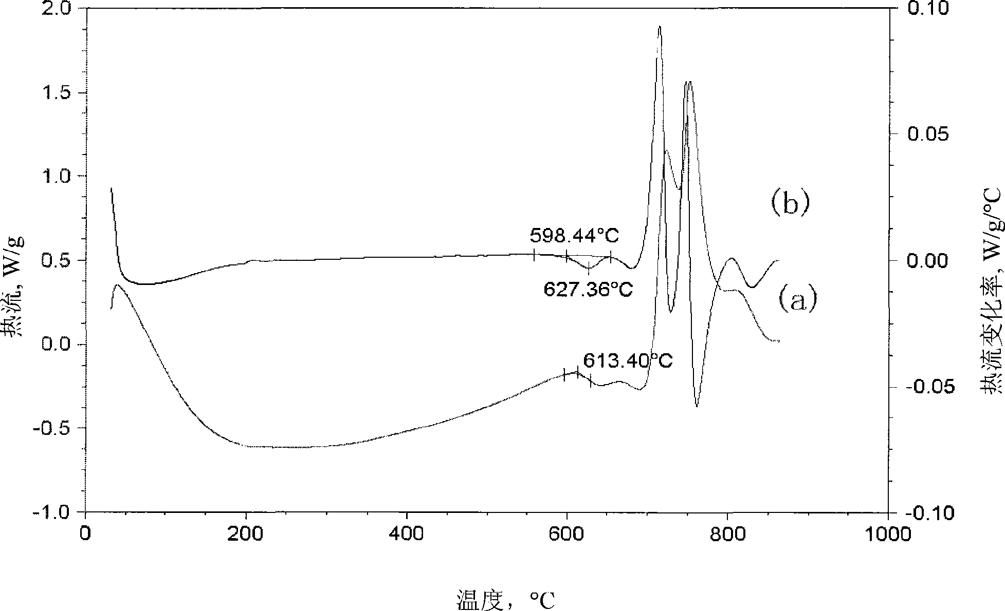
[0035] 2. Use a differential thermal analyzer to measure the heat flow-temperature curve of the sample obtained in step 1 under nitrogen atmosphere, 40°C / min, and DSC mode, see image 3 the a curve;

[0036] 3. The heat flow-temperature curve obtained in step 2 is derived from the temperature to obtain the heat flow rate-temperature curve, see image 3 the b-curve;

[0037] 4. On the heat flow rate-temperature curve obtained in step 3, find out the peak corresponding to the glass transition, and determine the onset temperature (T i )598.44℃, peak temperature (T P )627.36°C, thus determining the reference temperature range [1] as: from the initial temperature of 598.44°C (T i) to a peak temperature of 627.36°C (T P );

[0038] 5. On the heat flow-temperature curve, within a slightly wid...


PUM


Abstract

The invention discloses a thermal analysis method for measuring glass transition temperature of amorphous alloy. A determination method based on differential scanning calorimetry (hereinafter shortened as DSC) or differential thermal analysis (hereinafter shortened as DTA) adopts a DSC or DTA thermal analyser to establish a heat flux (temperature difference)-temperature curve of alloy and further evaluate a heat flux (temperature difference) change rate-temperature curve, thereby evaluating the reference temperature range of glass transition; and a maximum slope method is used to determine the glass transition temperature Tig or Teg within the analysis temperature range determined by the reference temperature range. The thermal analysis method adopts the DSC or DTA thermal analyser to finish the test, overcomes the disadvantages of poor accuracy and repetitiveness of an ordinary DSC or DTA method, is far popular than the application of special instruments such as a dilatometer and the like, and is particularly suitable for on-spot quality detection in production process.

Description

technical field [0001] The invention relates to two fields of amorphous alloy and thermal analysis testing technology, in particular to a thermal analysis method for measuring glass transition temperature of amorphous alloy. Background technique [0002] Amorphous alloys have good comprehensive mechanical properties and unique physical and chemical properties, and have broad application prospects in the future. Glass transition temperature T g It is one of the important indicators to measure the thermal stability of the alloy. [0003] There are currently two ways to measure T g The first is the thermal analysis method based on differential scanning calorimeter (hereinafter abbreviated as DSC) and differential thermal analyzer (hereinafter referred to as DTA). The baseline on the DTA curve changes, and this region corresponds to the glass transition process of the alloy. The degree of change of the baseline of different alloy systems is very different, and the degree of ...

Claims


Application Information

Patent Timeline
IPC IPC(8): G01N25/04
Inventor 谢致薇杨元政陈先朝温敦古卢国辉叶小薇
Owner GUANGDONG UNIV OF TECH
Why Eureka
Try Eureka