Ring-shaped vector light beam focusing system

A focusing system and a ring-shaped technology, applied in the field of optics, can solve problems such as limited application range, high requirements for incident beams, and difficulty in changing the shape and size of outgoing beams, achieving high stability and reliability, simple and convenient adjustment methods, and incident Effects with low beam requirements

Inactive Publication Date: 2009-08-12
UNIV OF SHANGHAI FOR SCI & TECH
View PDF1 Cites 10 Cited by
  • Summary
  • Abstract
  • Description
  • Claims
  • Application Information

AI Technical Summary

Problems solved by technology

In the prior art, there is an adjustable vector beam shaping system (see Chinese invention patent "Adjustable Vector Beam Shaping System", patent number: ZL200410052913.4), which can generate a certain vector beam and has Considerable advantages, but still there are some essential deficiencies, mainly: 1) if utilize prior art to produce the rotating vector polarized beam, the necessary condition is that the incident beam of the system must be the special form of the rotating vector polarized beam, such as radial However, the generation of radially polarized beams and azimuthally polarized beams also belongs to the category of rotating vector polarized beams, which essentially determines that it is impossible to convert non-rotating vector polarized beams into rotating

Method used


Image

  • Ring-shaped vector light beam focusing system

Examples


Embodiment Construction

[0022] The present invention will be described in further detail below in conjunction with the accompanying drawings and embodiments.

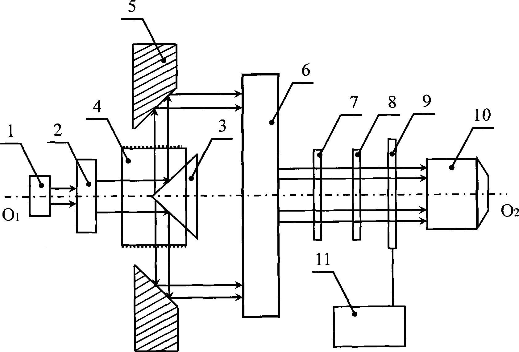
[0023] A circular vector beam focusing system, its structure is as follows figure 1 shown. Incident beam expander shaper 2, external reflection conical mirror 3, cylindrical curved polarizer 4, internal reflection cone mirror 5, exit beam expander shaper 6, entrance half-wave plate 7, exit The half-wave plate 8 , the spatial light modulator 9 and the objective lens 10 are sequentially arranged on the optical path of the light beam emitted by the light source 1 with the symmetrical optical axis; the spatial light modulator controller 11 is connected with the spatial light modulator 9 .

[0024] The reflective cone of the external reflective conical reflector 3 is parallel to the reflective conical of the internal reflective conical reflector 5, and the reflective cone of the external reflective conical reflector 3 and the internal reflective c...


PUM


Abstract

The invention relates to an annular vector light beam focusing system, which is characterized in that an incident beam-enlarging shaper, an external reflection circular conical surface reflecting mirror, a cylindrical curved surface polarizer, an internal reflection circular conical surface reflecting mirror, an emergent beam-enlarging shaper, an incident half-wave plate, an emergent half-wave plate, a spatial light modulator and an object lens are arranged on a light source emergent light beam light path in turn with the same symmetrical optical axis, wherein a spatial light modulator controller is connected with the spatial light modulator. The reflection conical surface of the external reflection circular conical surface reflecting mirror is parallel with that of the internal reflection circular conical surface reflecting mirror, and the included angles between the reflection conical surfaces of the external reflection circular conical surface reflecting mirror and the symmetrical optical axis and between the internal reflection circular conical surface reflecting mirror and the symmetrical optical axis is between 35 and 55 degrees respectively. The annular vector light beam focusing system has the advantages of low requirement on incident light beams, convenient adjustments of vector annular light beam output, light beam polarization state and horizontal size, adjustable and controllable wave front phases and the like.

Description

technical field [0001] The invention belongs to the field of optical technology, and relates to a beam focusing system, in particular to a circular vector beam focusing system. Mainly used in lithography, optical lighting, optical microscopy, laser micromachining, optical micromanipulation, optical information storage and other fields. Background technique [0002] The annular vector beam refers to the beam whose beam cross-section is annular and the polarization state exhibits rotational axis symmetry. Due to its unique focusing characteristics, it can be widely used in lithography, optical lighting, optical microscopy, laser micro Processing, optical micro-manipulation, optical information storage and other fields. For example, the ring beam focusing system can be applied to the optical microscope system to realize the super-resolution effect, because the focus of a certain rotation vector polarized beam after focusing is smaller than the transverse spot of the focus of t...

Claims


Application Information

Patent Timeline
IPC IPC(8): G02B27/09G02B27/46G02B7/182G02B5/30
Inventor 高秀敏郭汉明王琦李卓庄松林
Owner UNIV OF SHANGHAI FOR SCI & TECH
Why Eureka
Try Eureka