Composite tuner capable of preventing mutual interference between terrestrial broadcast and satellite broadcast
A satellite broadcasting and tuner technology, applied in the field of satellite and ground wave composite tuners, can solve problems such as interference signal quality and deterioration, achieve good reception characteristics, prevent radiation, and reduce power consumption.
- Summary
- Abstract
- Description
- Claims
- Application Information
AI Technical Summary
Problems solved by technology
Method used
Image
Examples
Embodiment 1
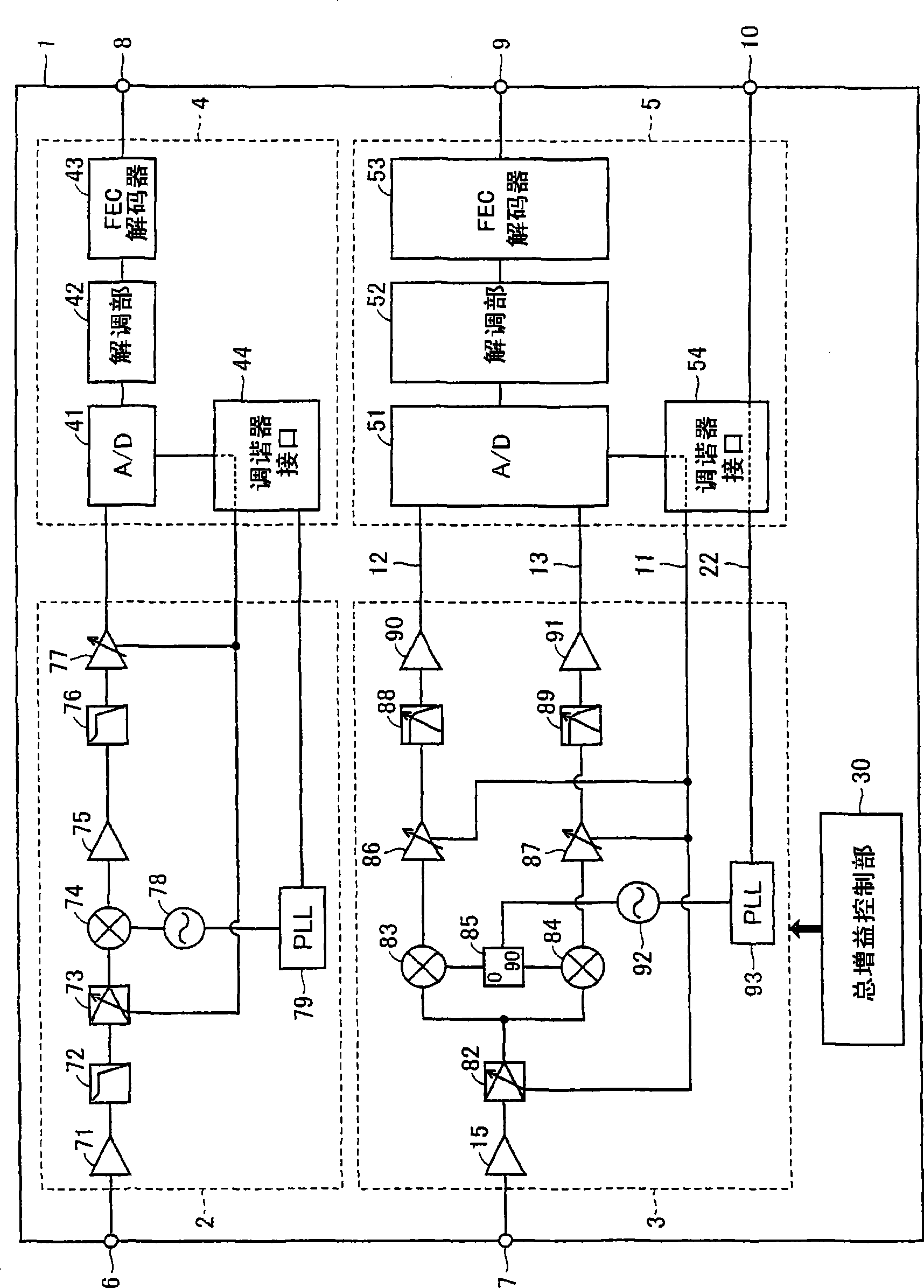
[0031] figure 1 It is a block diagram showing the basic configuration of the composite satellite and terrestrial wave tuner 1 according to the present invention.
[0032] refer to figure 1 , The basic structure of the satellite and terrestrial composite tuner 1 is to include a terrestrial broadcast tuner 2 , a satellite broadcast tuner 3 , a terrestrial broadcast demodulator 4 and a satellite broadcast demodulator 5 .
[0033] The composite satellite and terrestrial wave tuner 1 further includes a terminal 6 to which a terrestrial broadcast signal is input, a terminal 7 to which a satellite broadcast signal is input, a terminal 8 to which a transport stream signal of a terrestrial broadcast is output, and a terminal to which a transport stream signal of a satellite broadcast is output. 9, and I2C terminal 10. The I2C terminal 10 is connected to a microcontroller provided in a broadcast receiver in which the composite satellite and terrestrial tuner 1 is installed. The compo...
Embodiment 2
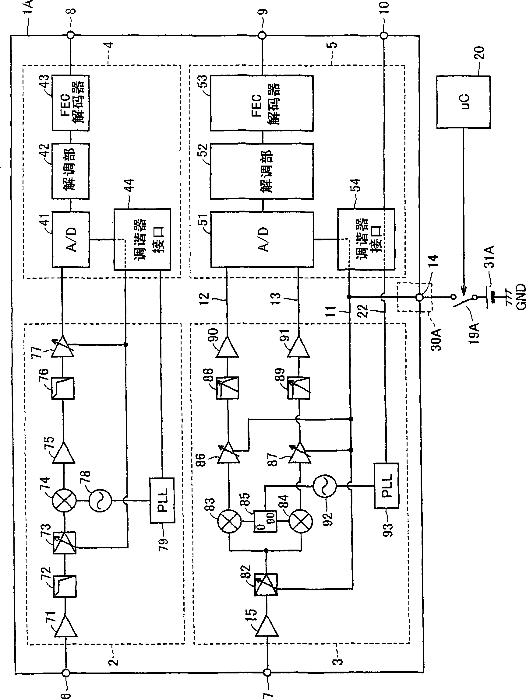
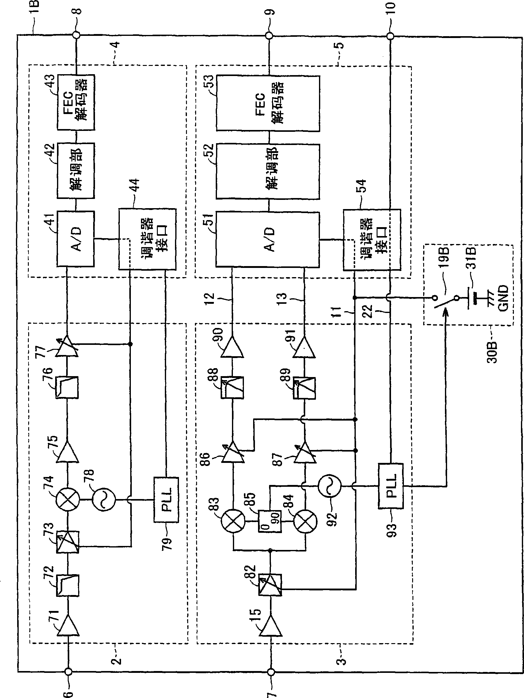
[0061] image 3 It is a block diagram showing the configuration of a composite satellite and terrestrial wave tuner 1B according to Embodiment 2 of the present invention. image 3 express figure 1 A specific example of the configuration of the overall gain control unit 30.
[0062] refer to image 3 The overall gain control unit 30B includes a DC power supply 31B and a switch circuit 19B connected between the AGC signal line 11 and the output node of the DC power supply 31B. The power supply voltage is applied to or cut off from the AGC signal line 11 by the switch circuit 19B. Here, the switch circuit 19B is switched to an on state or an off state according to a control signal supplied from the tuner control unit 93 of the satellite broadcast tuner unit 3 . Information on the operation mode of the satellite broadcast demodulation unit 5 and the like are supplied from the microcontroller 20 to the tuner control unit 93 through the I2C terminal 10 . Thus, in the second emb...
Embodiment 3
[0066] Figure 4 It is a block diagram showing the configuration of a satellite / terrestrial composite tuner 1C according to Embodiment 3 of the present invention. Figure 4 express figure 1 A specific example of the configuration of the overall gain control unit 30.
[0067] refer to Figure 4 The overall gain control unit 30C includes a dedicated power supply terminal 16 for supplying a power supply voltage 31C to the high-frequency amplifier 15 of the satellite broadcast tuner unit 3 . The power supply terminal 16 is connected to a switch circuit 19C for supplying or cutting off a power supply voltage 31C. Switching of the switch circuit 19C to an on state or an off state is controlled by the microcontroller 20 that controls the entire broadcast receiver.
[0068] When receiving satellite broadcasting, microcontroller 20 turns on switching circuit 19C to supply power supply voltage 31C to high frequency amplifier 15 . When the satellite broadcast is not received, the mi...
PUM
 Abstract
Description
Claims
Application Information
 - R&D Engineer
- R&D Manager
- IP Professional
- Industry Leading Data Capabilities
- Powerful AI technology
- Patent DNA Extraction
Browse by: Latest US Patents, China's latest patents, Technical Efficacy Thesaurus, Application Domain, Technology Topic, Popular Technical Reports.
© 2024 PatSnap. All rights reserved.Legal|Privacy policy|Modern Slavery Act Transparency Statement|Sitemap|About US| Contact US: help@patsnap.com


