Building block system type tube stretcher
A tension reducer and building block technology, applied in the field of steel rolling equipment, can solve the problem of "dropping" speed of a single-drive tension reducer, and achieve the effects of reduced floor space, reduced total weight and simple structure
- Summary
- Abstract
- Description
- Claims
- Application Information
AI Technical Summary
Problems solved by technology
Method used
Image
Examples
Embodiment approach 2
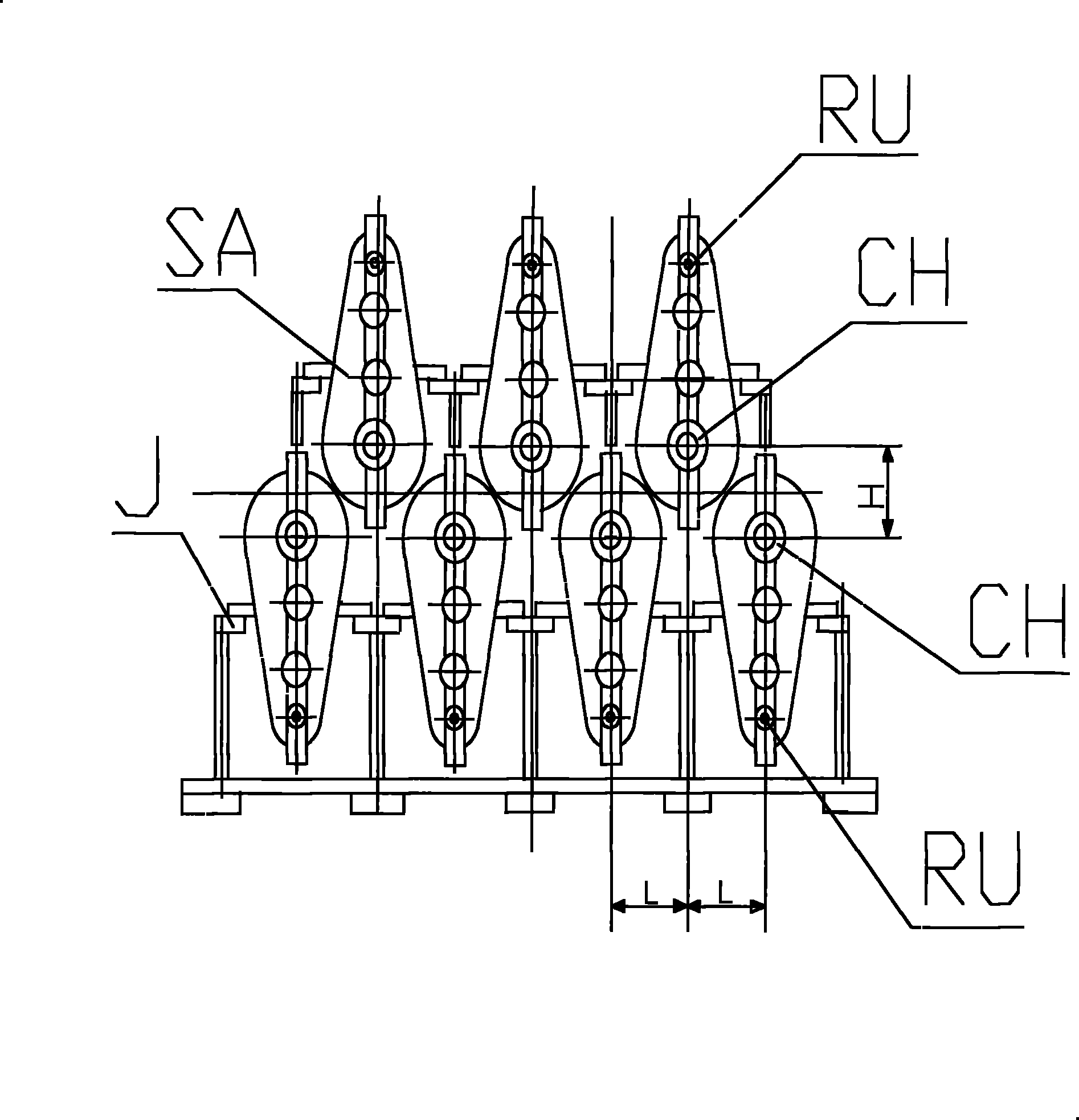
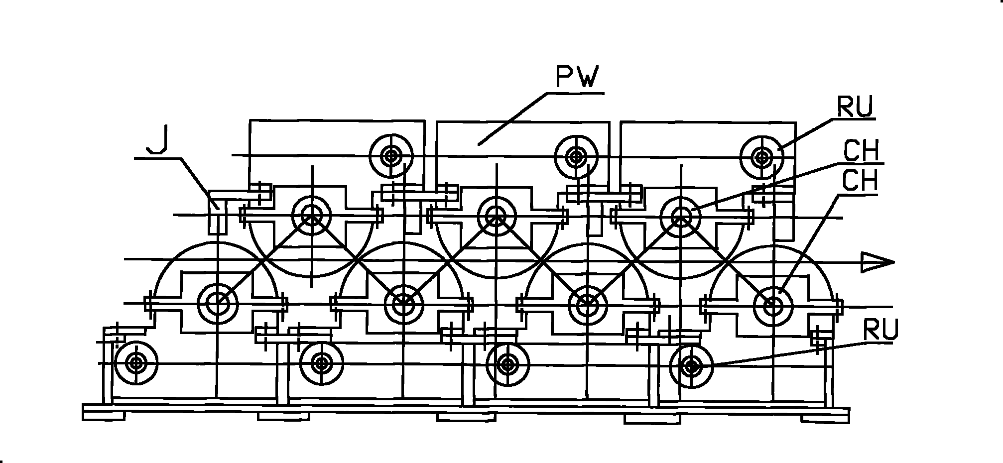
[0040] Embodiment 2, with image 3 The seven-frame plane secondary enveloping toroidal worm reducer PW type steel pipe tension reducer is shown as an example. The seven plane secondary enveloping toroidal worm reducers PW are exactly the same, and the installation directions are different. They are divided into upper and lower floors. The upper three planar double-enveloping toroidal worm reducers PW are vertically arranged, the output shaft CH is on the bottom, and the input shaft RU is on the top; the lower four planar double-enveloping toroidal worm reducers PW are also vertically arranged, but the output The shaft CH is at the top and the input shaft RU is at the bottom. Seven plane secondary enveloping toroidal worm reducers PW are installed on the welding bracket J in sequence. The schematic diagram of the transmission is attached Figure 4 shown.
[0041] Except that the bracket needs to be designed according to the installation size of the secondary enveloping toroi...
Embodiment approach 3
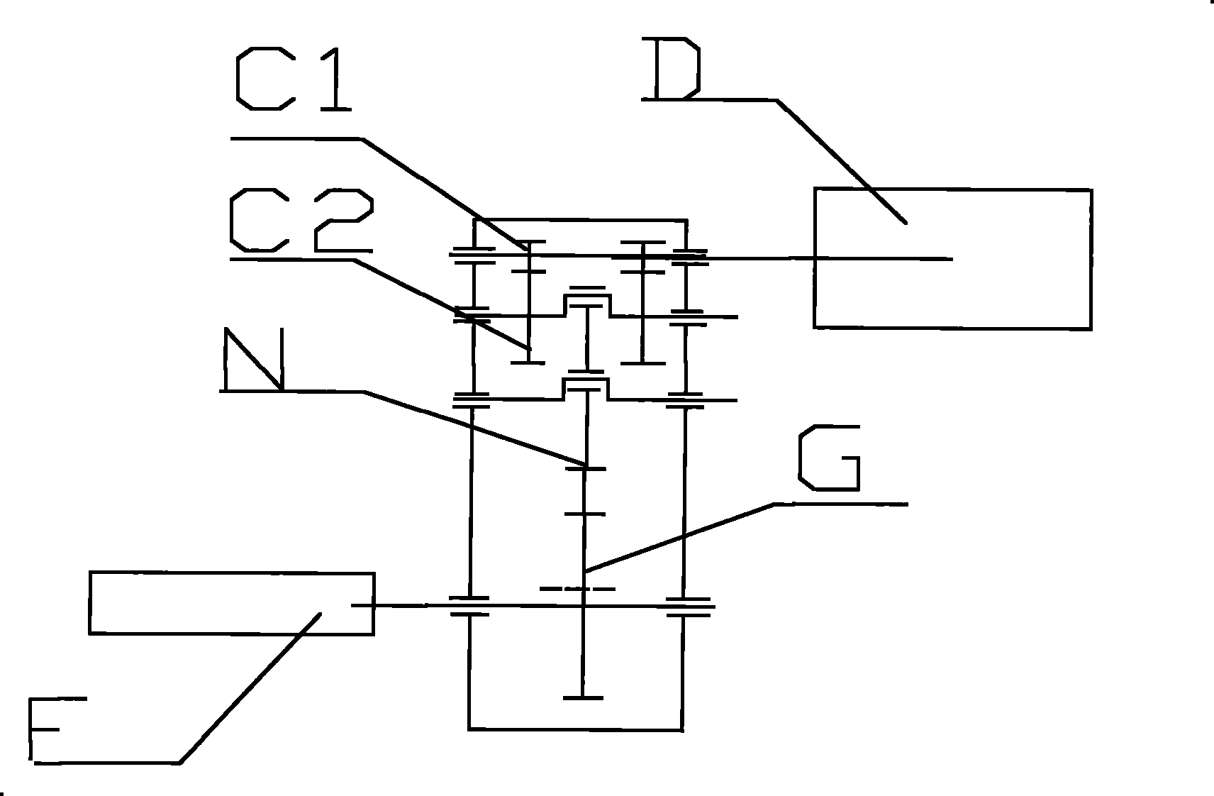
[0043] Embodiment 3, attached figure 2It is the transmission schematic diagram of a single three-ring reducer. The speed regulating motor D drives the gear C1, and then drives the gear C2 and the crankshaft of the three-ring reducer connected with it. The output gear G is connected with the output shaft CH to drive the roll stand. Others are the same as Embodiment 1.
Embodiment approach 4
[0044] Embodiment 4, attached Figure 4 It is a schematic diagram of the transmission of a single plane quadratic enveloping toroidal worm reducer. The speed regulating motor drives the bevel gear at z1, and then drives the bevel gear z2 and the worm WG connected with it, and the output shaft CH is connected with the worm wheel WL to drive the roll stand. Others are the same as Embodiment 1.
PUM
 Abstract
Description
Claims
Application Information
 - R&D
- Intellectual Property
- Life Sciences
- Materials
- Tech Scout
- Unparalleled Data Quality
- Higher Quality Content
- 60% Fewer Hallucinations
Browse by: Latest US Patents, China's latest patents, Technical Efficacy Thesaurus, Application Domain, Technology Topic, Popular Technical Reports.
© 2025 PatSnap. All rights reserved.Legal|Privacy policy|Modern Slavery Act Transparency Statement|Sitemap|About US| Contact US: help@patsnap.com


