
Double-magazine double main-shaft machine tool for processing two-end holes of crankshaft

A dual-spindle and hole processing technology, which is applied to metal processing machinery parts, metal processing equipment, manufacturing tools, etc., can solve the problems of narrow processing range, expensive power head, low power, etc.

Inactive Publication Date: 2009-08-19
SHENYANG AEROSPACE UNIVERSITY
View PDF0 Cites 18 Cited by
  • Summary
  • Abstract
  • Description
  • Claims
  • Application Information

AI Technical Summary

Problems solved by technology

[0002] In the general crankshaft processing technology, the holes at both ends are processed by two or more lathes respectively. The main problem of this processing method is the difference in the coaxiality of the center hole.
Later, a machine tool for machining holes at both ends of the crankshaft with two power heads on the left and right of the machine tool appeared. However, the power head of this machine tool is relatively expensive, the power is low, and the cutting efficiency is low. It cannot process large locomotive crankshafts and small and medium-sized marine crankshafts. Large workpieces, and due to the limitation of the structure of the power head, the types and quantities of tools on the power head are small, and the processing range is narrow

Method used


Image

  • Double-magazine double main-shaft machine tool for processing two-end holes of crankshaft
  • Double-magazine double main-shaft machine tool for processing two-end holes of crankshaft
  • Double-magazine double main-shaft machine tool for processing two-end holes of crankshaft

Examples


Embodiment Construction

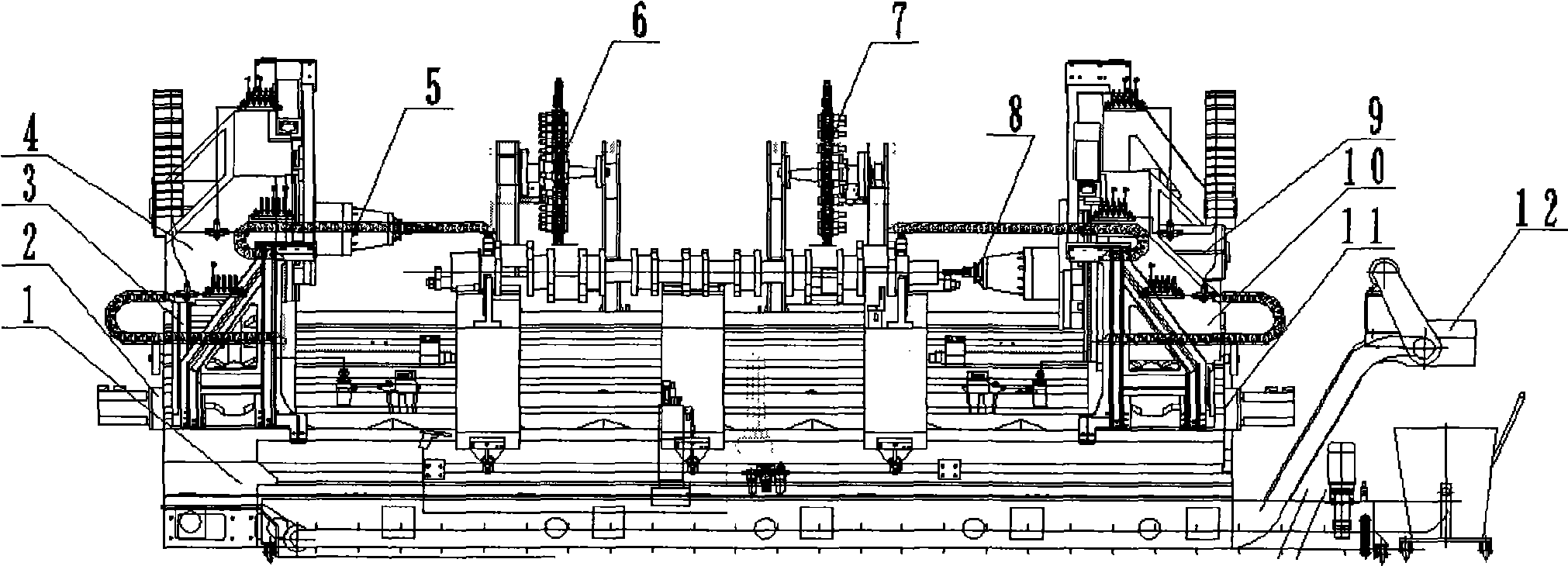
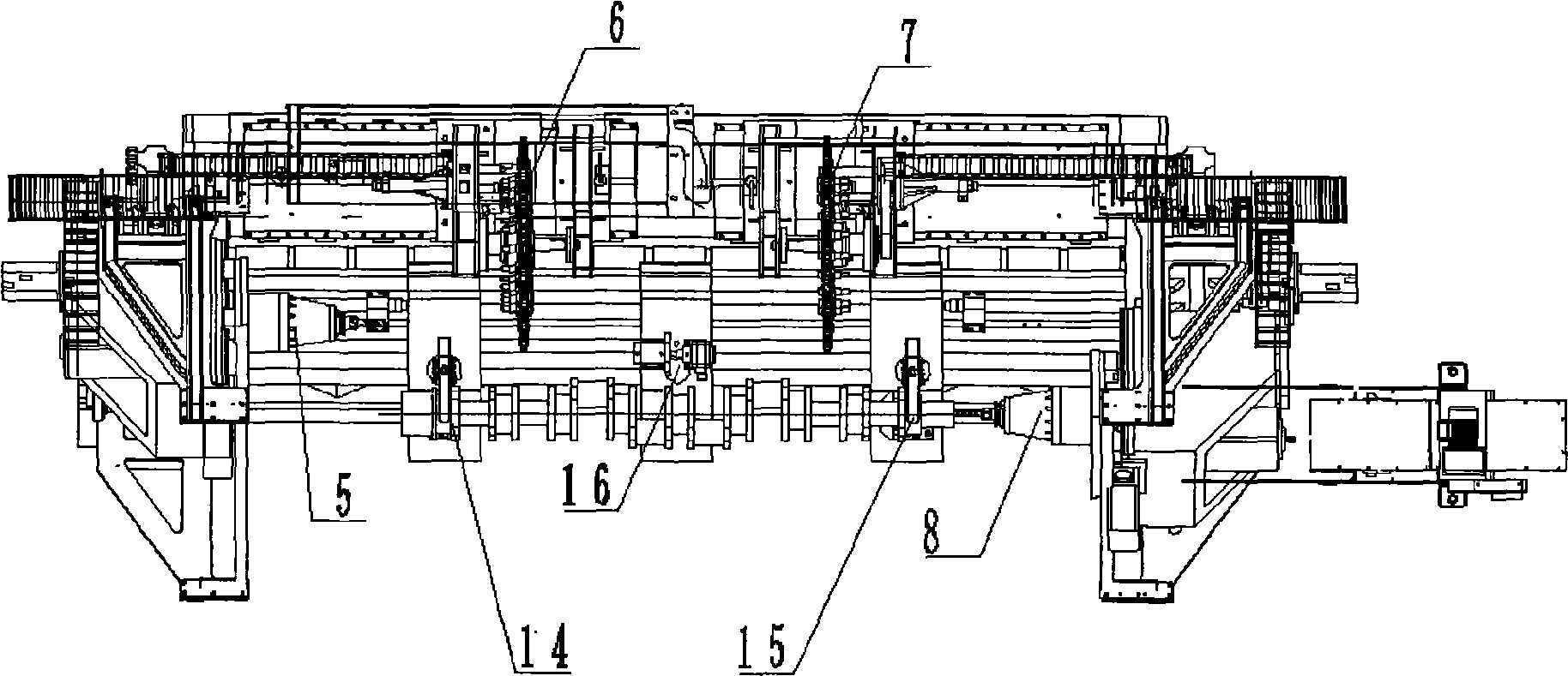
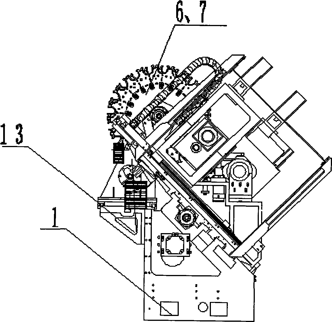
[0012] Such as Figure 1-Figure 6 As shown, the dual-spindle and dual-tool magazine special CNC machine tool with holes at both ends of the crankshaft includes an integral casting 45° inclined bed (1) for easy chip removal, a left Z-axis screw component (2), and a left X-axis saddle component ( 3), left Y-axis component (4), left spindle (5), left tool magazine (6), right tool magazine (7), right spindle (8), right Y-axis component (9), right X-axis sliding saddle Piece (10), right Z-axis screw component (11), chip cooling component (12), tool magazine carriage (13), left clamp (14), right clamp (15), bracket (16). The left main shaft (5) is installed on the left Y-axis component (4), the left Y-axis component (4) is installed on the left X-axis saddle component (3), and the left X-axis saddle component (3) is installed on the left Z-axis On the screw component (2), these four components are assembled together to form the left three-coordinate unit. In the same way, the right main ...


PUM


Abstract

The invention relates to a double-magazine-tool and double-spindle crankshaft two-end hole processing machine tool, which comprises an integral casting 45 degree inclined machine tool body which is convenient for removing scraps. The machine tool body is provided with two sets of three-coordinate units left and right symmetrically, and the three-coordinate units consist of a left Z-axis screw rod part and a right Z-axis screw rod part, a left X-axis saddle part and a right X-axis saddle part, and a left Y-axis part and a right Y-axis part respectively. A left spindle and a right spindle are arranged on the two sets of the three-coordinate units respectively. A left magazine tool and a right magazine tool can be connected with the left Z-axis screw rod part and the right Z-axis screw rod part respectively, and move along the direction of Z along with the spindles through the support of a magazine tool slide frame. The machine tool not only has the function of processing various holes at both ends of the crankshaft, but also can tap and chamfer corners. Aiming at the crankshafts of different specifications, the distance between the left processing spindle and the right processing spindle is guaranteed by adjusting both the left three-coordinate unit and the right three-coordinate unit of the machine tool so as to adapt to the crankshafts of different lengths, and cutter tools in the magazine tools are replaced to adapt to different processing tasks.

Description

Technical field: [0001] The invention relates to a machine tool, in particular to a double-tool magazine and double-spindle crankshaft two-end hole machining machine tool, which belongs to the field of mechanical equipment processing and is mainly used for processing large-scale locomotive crankshafts and medium and small-sized marine crankshafts. Background technique: [0002] In the general crankshaft processing technology, the holes at both ends are processed by more than two lathes. The main problem of this processing method is the poor coaxiality of the center hole. Later, there appeared a crankshaft end hole machining machine tool with two power heads on the left and right sides of the machine tool, but the power head of this machine tool is more expensive, low power, low cutting efficiency, and cannot process large locomotive crankshafts and small and medium-sized marine crankshafts. Large workpieces, and due to the limitation of the power head structure, there are fewer t...

Claims


Application Information

Patent Timeline
IPC IPC(8): B23B39/16B23B41/00B23Q3/157
Inventor 王明海张彦富刘中海王虎军
Owner SHENYANG AEROSPACE UNIVERSITY
Learn More