
Connection method between cam and axle tube of jacket assembling cam shaft

A camshaft and cam technology, which is applied to valve devices, engine components, machines/engines, etc., can solve the problems of poor use effect, weak cam connection, short life, etc.

Inactive Publication Date: 2009-08-19
河南中轴集团有限公司
View PDF0 Cites 2 Cited by
  • Summary
  • Abstract
  • Description
  • Claims
  • Application Information

AI Technical Summary

Problems solved by technology

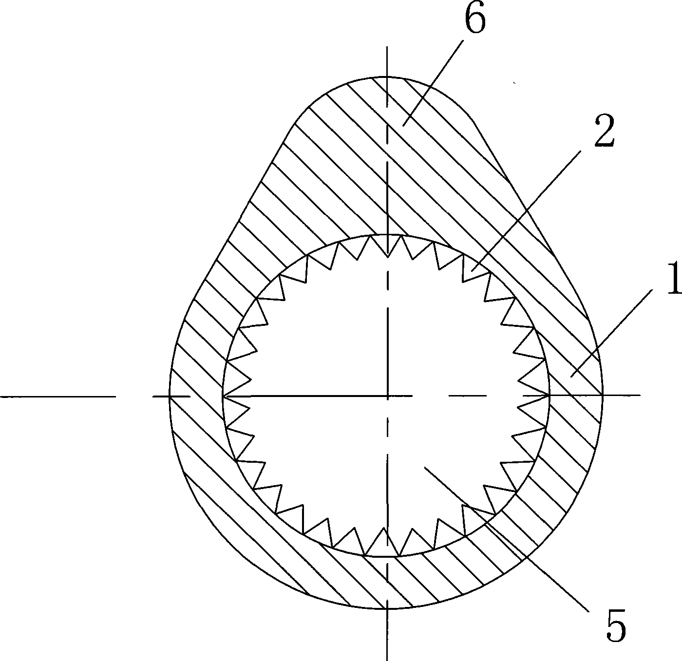
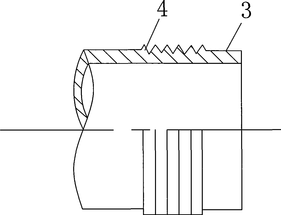
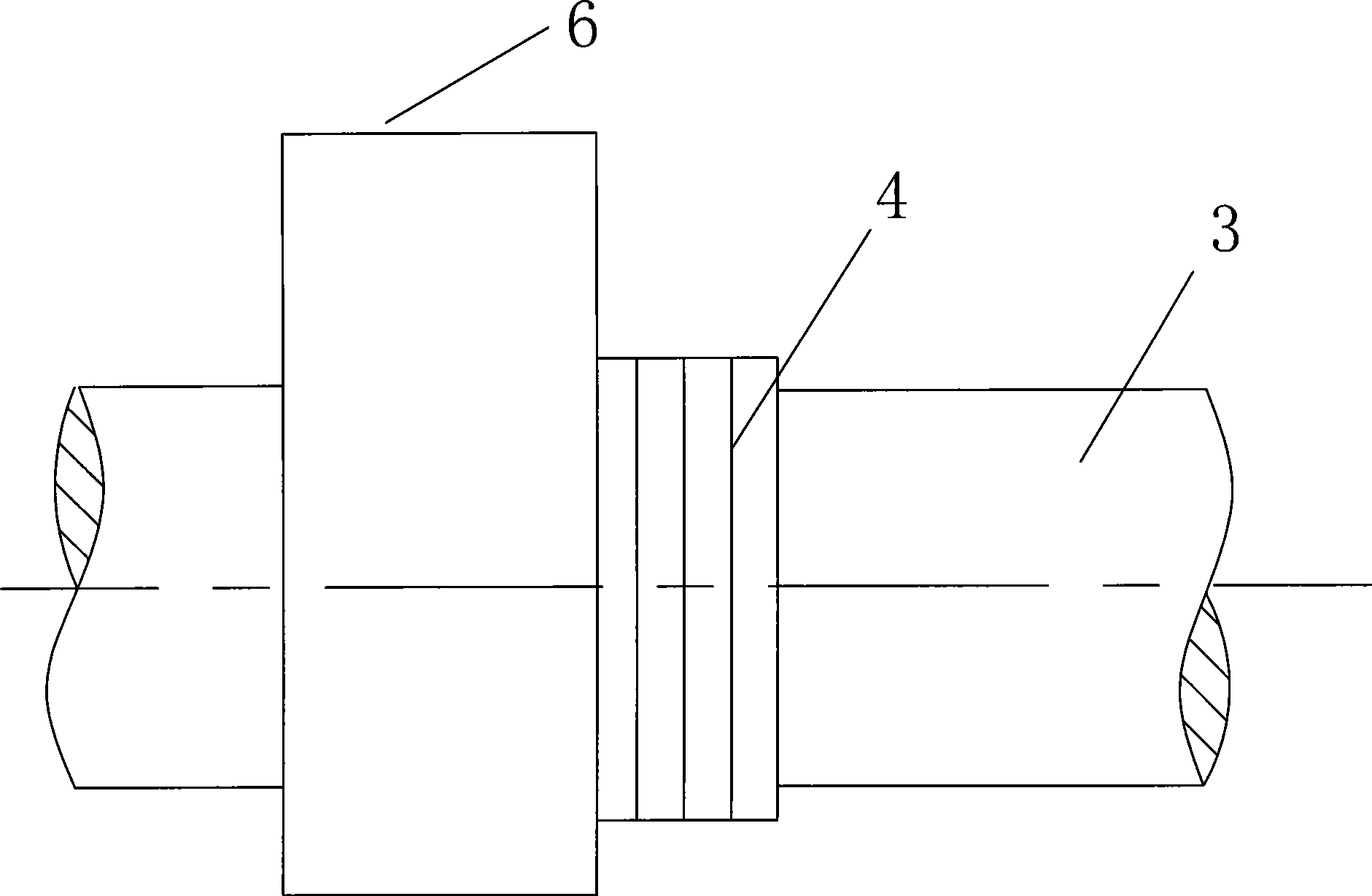
[0003] The purpose of the present invention is to provide a method for connecting the cam and the shaft tube of the fitted camshaft, which can effectively solve the problems of weak connection, poor use effect and short service life of the cam. The hole is machined with straight knurling or teeth, and then the outer surface of the shaft tube is fitted with a cam, and a thread or an annular groove is processed, and then the thread or an annular groove on the outer surface of the shaft tube is fitted on the cam with pressure. The straight knurling or teeth on the surface of the inner hole make the thread or annular groove on the outer surface of the shaft tube intersect with the straight knurling or teeth on the inner surface of the cam to form the cam and the shaft tube. Firm integrated structure, the method of the present invention is simple, the connection is firm, the cost is low, the production efficiency is high, the service life of the product is long, and it is easy to realize industrial automation production

Method used


Image

  • Connection method between cam and axle tube of jacket assembling cam shaft
  • Connection method between cam and axle tube of jacket assembling cam shaft
  • Connection method between cam and axle tube of jacket assembling cam shaft

Examples


example 1

[0011] Example 1. In the actual production of the present invention, the cam 1 and the shaft tube can adopt the shrink-fit mechanical extrusion method. The specific steps are: first, straight grain knurling or teeth 2 are evenly processed on the surface of the inner hole 5 of the cam 1, and the straight grain knurling The flower or tooth modulus is 0.3-0.5, and then the outer surface of the shaft tube 3 is fitted with a cam, and the thread or annular groove 4 corresponding to the straight grain knurling or tooth 2 is evenly processed, and the thread or annular groove The groove 4 pitch is 0.8—2.0mm, and then the cam is heated to 150°C-300°C, and then the threads or annular grooves on the outer surface are pressure-fitted on the straight grain knurling or teeth on the surface of the inner hole of the cam , so that the threads or annular grooves 4 on the outer surface of the shaft tube 3 and the straight knurls or teeth on the surface of the inner hole of the cam intersect and en...

example 2

[0012] Example 2. In the actual production of the present invention, the cam 1 and the shaft tube can also adopt the internal expansion tooth embedding method. The steps are: firstly, the surface of the inner hole 5 of the cam 1 is uniformly processed with straight grain knurling or teeth 2, and then The outer surface of the shaft tube 3 is fitted with the cam, and the threads or annular grooves 4 corresponding to the straight grain knurling or teeth are uniformly processed, and then the threads or annular grooves 4 on the outer surface of the shaft tube are applied with internal high pressure (The pressure is determined according to the specifications and models of different products.) The shaft tube and the cam are expanded, and the straight knurling or teeth of the cam are firmly embedded in the outer surface of the shaft tube, so that the cam and the shaft tube are firmly connected.

[0013] The invention changes the traditional connection form in which the inner hole of th...


PUM


Abstract

The invention relates to a method for connecting a cam and a shaft tube of a set assembled camshaft, which can effectively resolve the problems of infirm connection of the cam, poor utilization effect and short service life. The resolution technical proposal is as follows: firstly processing straight knurlings or cogs at the inner hole of the cam, processing threads or circular grooves at the position of the external surface of the shaft tube, the position where the cam is sheath, and the threads or the circular grooves on the external surface of the shaft tube are pressed on the straight knurlings or cogs at the inner hole of the cam for embedding in a mutually crossed way so as to construct a firm integral structure of the cam and the shaft tube. For the invention, the method is simple, the connection is firm, the cost is low, the productivity is high, the service life of the product is long, and industrial automatic production can be realized easily.

Description

1. Technical field [0001] The invention relates to a method for connecting a cam and a shaft tube of an overfitting camshaft. 2. Background technology [0002] The assembled camshaft is a new type of automobile engine camshaft, which is made by pre-forging or casting the cam, and then fitting the cam on the steel pipe (shaft tube). Due to the problem of the connection method, the cam connection of the existing shaft head is not firm, the use effect is poor, and the life is short. The shaft head is the part of the camshaft that bears the largest torque. Therefore, how to firmly connect the shaft head to the shaft tube is a One of the key technologies for manufacturing assembled camshafts. 3. Contents of the invention [0003] The purpose of the present invention is to provide a method for connecting the cam and the shaft tube of the fitted camshaft, which can effectively solve the problems of weak connection, poor use effect and short service life of the cam. The hole is ...

Claims


Application Information

Patent Timeline
IPC IPC(8): F01L1/047
Inventor 关洪涛苗祥利任学勤朱天合赵娟
Owner 河南中轴集团有限公司
Learn More