Liquid level sensor

A technology of liquid level sensor and Hall device, which is applied in the direction of buoy liquid level indicator, etc., can solve the problems of easy corrosion, circuit breakage, and difficult to greatly improve the service life, and achieve the effect of simplifying the processing circuit and improving the service life

Active Publication Date: 2009-08-19
UNITED AUTOMOTIVE ELECTRONICS SYST
View PDF0 Cites 4 Cited by
  • Summary
  • Abstract
  • Description
  • Claims
  • Application Information

AI Technical Summary

Problems solved by technology

This kind of potentiometer sensor, on the one hand, has contact friction in the working process, and the service life is not easy to be greatly improved; on the other hand, due to the limitation of the used materials, it is prone to corrosion under complex oil products, causing circuit breakage or poor signal quality. Stable; moreover, due to the resistance output, the signal cannot be directly used by the vehicle instrument, and additional circuit design is required for signal conversion

Method used


Image

  • Liquid level sensor
  • Liquid level sensor
  • Liquid level sensor

Examples


Embodiment Construction

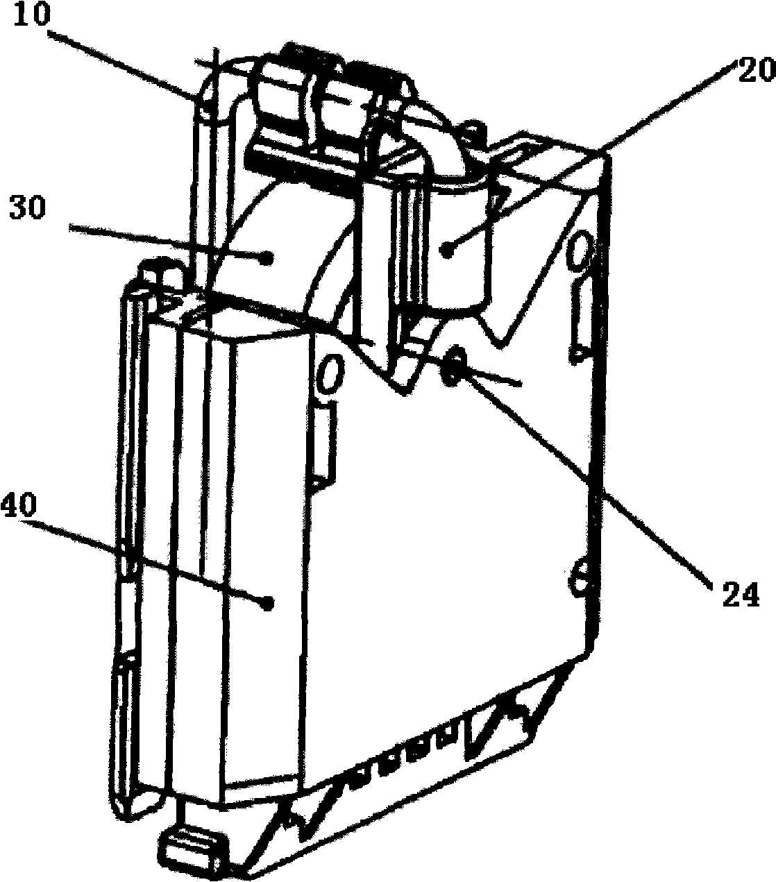
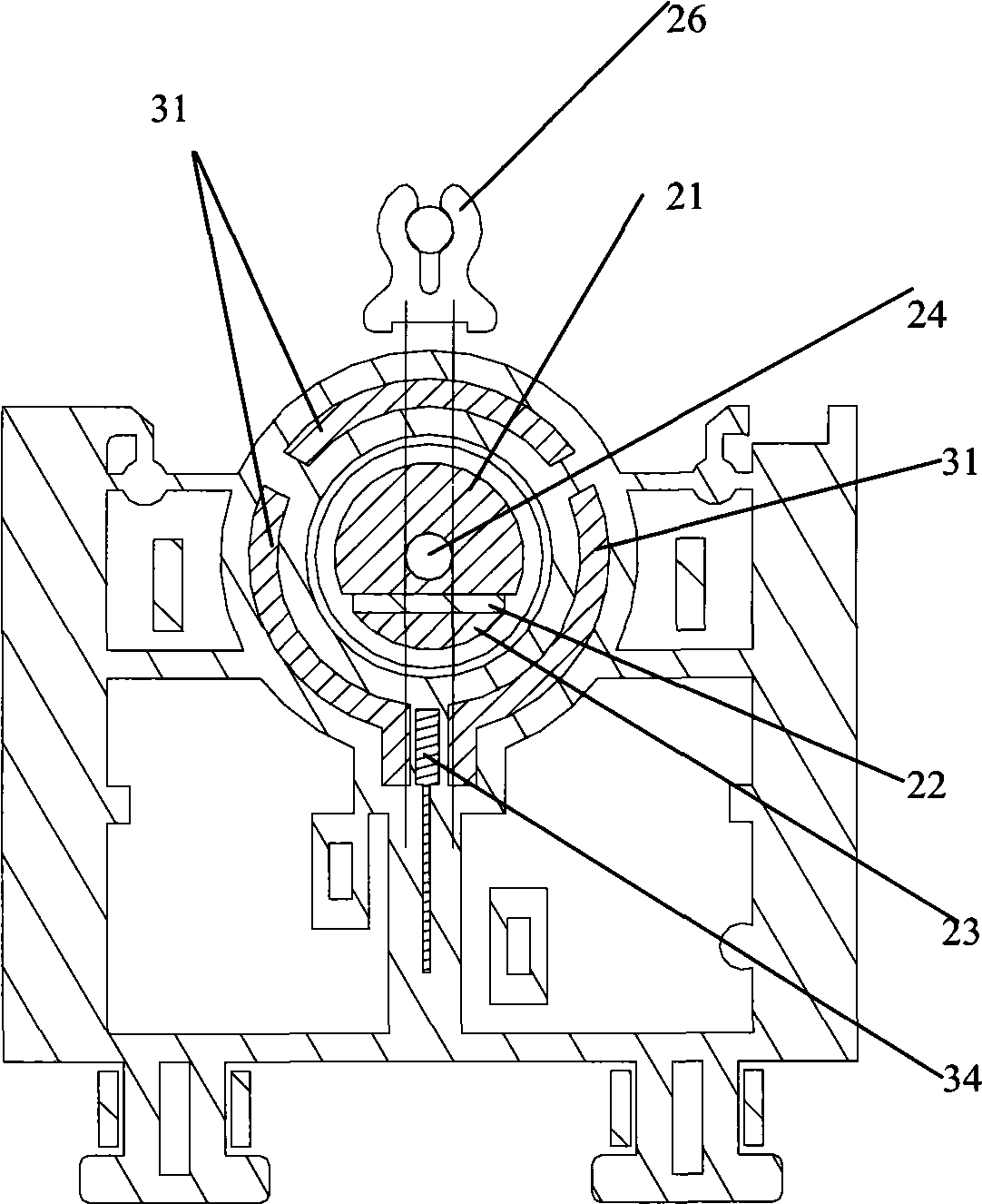
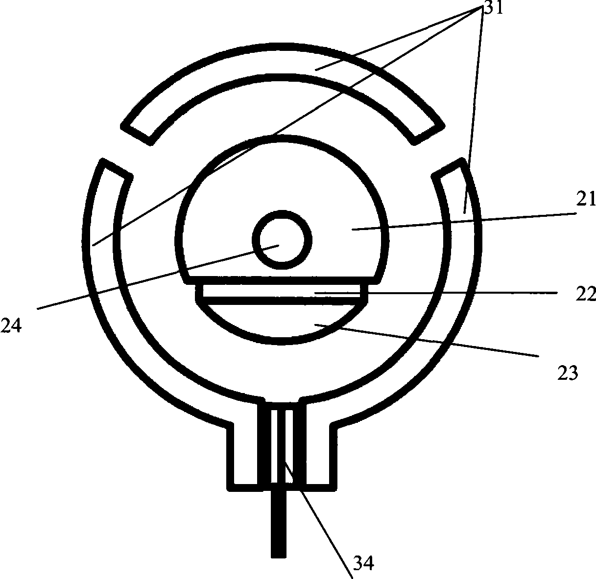
[0012] An embodiment of the liquid level sensor of the present invention is as follows: figure 1 , figure 2 As shown, it includes a rotor 20, a stator 30, a float assembly 10, and a side cover 40; the rotor is as figure 2 , image 3 As shown, it includes a support buckle 26, a rotary shaft 24, a larger soft iron one 21, a smaller soft iron two 23, a magnet 22, and a cylindrical plastic shell one. The magnet 22 is clamped on the soft iron Between iron one 21 and soft iron two 23, soft iron one 21, magnet 22, and soft iron two 23 form a cylinder together, and the axis of the cylinder formed together is provided with a circular hole one, and the soft iron one 21 exceeds Half of the cylinder formed together in the axial direction, the round hole one is set in the soft iron one 21, the rotary shaft 24 is sleeved in the round hole one, and the ends one and two end protrude out. The soft iron one 21, soft iron two 23, magnet 22 and the middle part of the rotary shaft 24 of the r...


PUM


Abstract

The invention discloses a liquid level sensor and uses the Hall effect principle. A rotor firmly connected with a floater component winds back to a rotating shaft and rotates when the liquid level changes, thus causing the change of peripheral magnetic field. As the magnetic field applied on a Hall device changes, the change of an output signal is realized. The specific spatial layout of the rotor, stator soft iron and the Hall device forms a specific magnetic circuit, thus leading the rotation angle of the rotor to form linear relation with the intensity of the magnetic field and the intensity of the magnetic field to form linear relation with the output voltage of the Hall device. Consequently, the linearity between the rotation angle of the rotor and the voltage signal output of the whole liquid level sensor is realized. The liquid level sensor has long service life and the output signal can be directly used by a vehicle instrument.

Description

technical field [0001] The invention relates to automobile electronic technology, in particular to a liquid level sensor. Background technique [0002] The current type of fuel position sensor for vehicles is a wire-wound resistor or a thick-film resistive potentiometer sensor, which consists of a resistor body and a rotating or sliding system. By rotating or sliding the system, the position of the contact on the resistor body is changed to obtain a The resistance that has a certain relationship with the position of the movable contact is a contact mechanism. This kind of potentiometer sensor, on the one hand, has contact friction in the working process, and the service life is not easy to be greatly improved; on the other hand, due to the limitation of the used materials, it is prone to corrosion under complex oil products, causing circuit breakage or poor signal quality. Stable; moreover, because it is a resistance output, the signal cannot be directly used by the vehicle...

Claims


Application Information

Patent Timeline
Patent Type & Authority Applications(China)
IPC IPC(8): G01F23/38
Inventor 李书龙柳朝华黄佳健屈晨竹
Owner UNITED AUTOMOTIVE ELECTRONICS SYST
Why Eureka
Try Eureka