
Dynamic target modulation transfer function measurement method

A technology of modulating transfer function and dynamic target, which is applied in the direction of testing optical performance, etc., and can solve the problems of not considering noise, not taking into account, not explaining point light source, etc.

Inactive Publication Date: 2009-08-19
HARBIN INST OF TECH
View PDF1 Cites 22 Cited by
  • Summary
  • Abstract
  • Description
  • Claims
  • Application Information

AI Technical Summary

Problems solved by technology

This method considers that the size of the point light source is negligible, and by selecting a small interval, the dark current of the image sensor outside the interval and the noise introduced by the background light can be filtered out, but its disadvantages are: ① It does not consider The influence of diffraction and aberration of the lens on the measurement results of the transfer function during the imaging process; ② did not take into account the influence of the dark current of the image sensor and the background light on the measurement results of the transfer function within the selected range; ③ no Explain the effect of the target on the transfer function measurement results when the size of the point source is not negligible
But its shortcoming is that it does not take into account the background light and the dark current of the image sensor introduced to the noise of the static target image and the dynamic target image, and finally makes the measurement result of the dynamic target modulation transfer function glitchy.

Method used


Image

  • Dynamic target modulation transfer function measurement method
  • Dynamic target modulation transfer function measurement method
  • Dynamic target modulation transfer function measurement method

Examples


example 1

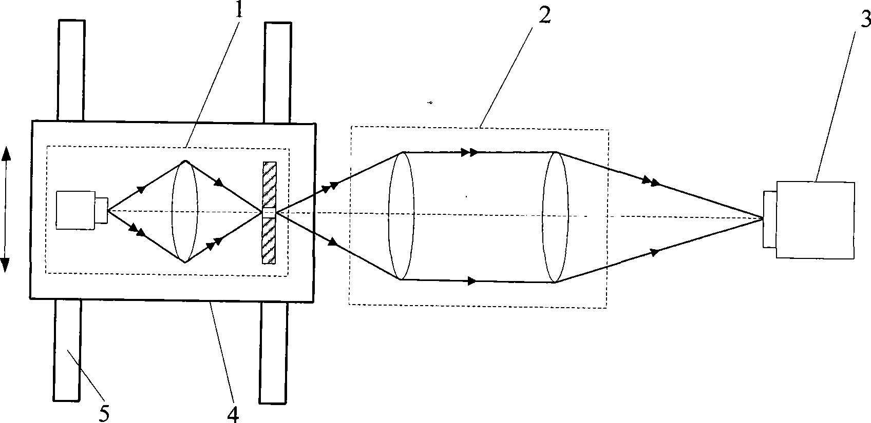
[0064] The method for measuring the dynamic target modulation transfer function of the present invention has the following steps:

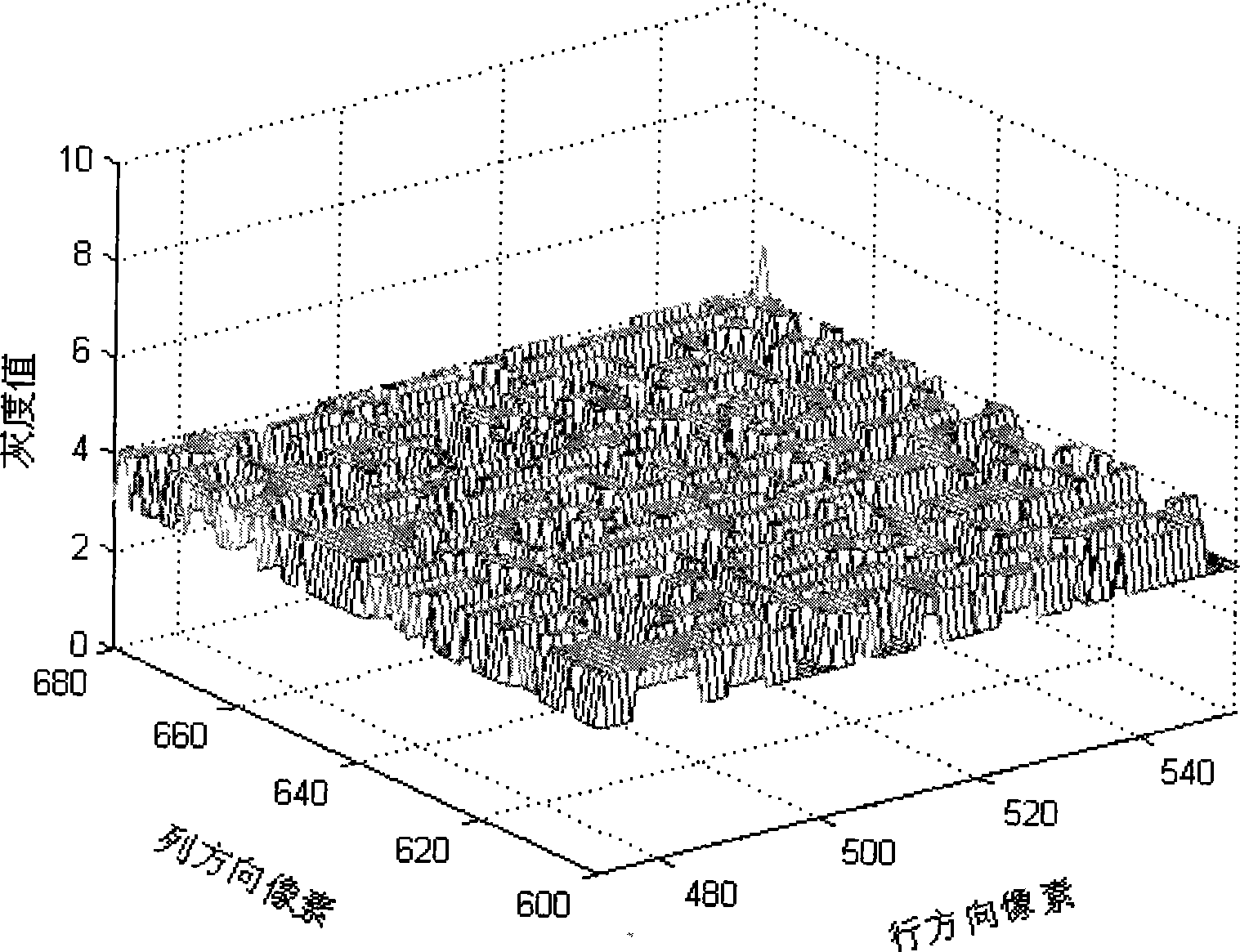
[0065] a. Under the condition of turning off the point light source 1, the image sensor 3 forms an image, and the recorded image sensor dark current and the synthetic interference image of the background image are as follows: figure 2 As shown, it can be seen that the dark current of the image sensor and the background image make the synthetic interference image have noise with a gray value of 3 or 4.

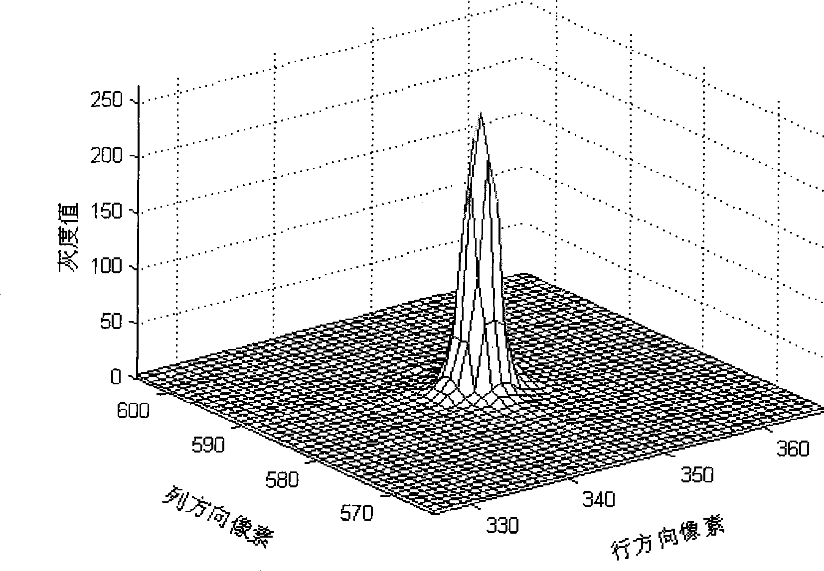
[0066] b. On the basis of step a, without changing any conditions except the point light source 1, light the point light source 1 and keep it still relative to the measurement system, the image sensor 3 is imaged, and the recorded dark current of the image sensor, Background images as well as synthetic static images of static objects such as image 3 shown. Figure 4 for image 3 It can be seen from this figure that the noise gray value of the ...

example 2

[0085] The corresponding measuring device and the parameters of the device in this embodiment are completely consistent with embodiment 1, and the first a, b, c, d, e steps of the measuring method are also completely consistent with embodiment 1, and the f, g, h, The i-step method is as follows:

[0086] f. Correct the de-interference static image obtained in step d, eliminate the residual information randomly introduced into the de-interference static image by the background light and the dark current of the image sensor, and the obtained secondary corrected static image is as follows Figure 18 as shown, Figure 19 for Figure 18 It can be seen from this figure that this step has corrected the noise gray value in the de-interference static image to 0.

[0087] g. Correct the de-interference dynamic image obtained in step e, and eliminate the residual information introduced into the de-interference dynamic image randomly by the background light and the dark current of the i...


PUM


Abstract

A measuring method for dynamic object modulation transfer function belongs to the test field of optical properties. The invention aims to provide a measuring method for dynamic object modulation transfer function that can not only remove background vagabond ray and dark current of an image sensor, but also remove nonideal target size and the effect on a measuring result by the diffraction and aberration defect of an optical system. The method first respectively records an interference image, a still image and a dynamic image through imaging under the condition of closing and lightening a point light source, keeping the light source still and moving the light source, respectively uses the still image, the dynamic image and the interference image to do subtraction and obtain an anti-interference still image and an anti-interference dynamic image, extracts and modifies line spread function therein to obtain modified static and dynamic object line spread functions and obtains initial static and dynamic object modulation transfer functions through Fourier transformation. And finally, the method uses the initial dynamic object modulation transfer function to be divided by the initial static object modulation transfer function, thus obtaining the final measuring result of the dynamic object modulation transfer function.

Description

technical field [0001] The invention relates to a measurement method of a modulation transfer function in the field of optical property testing, in particular to a measurement method of a dynamic target modulation transfer function. Background technique [0002] The modulation transfer function of a dynamic target is an important parameter to quantitatively describe the degree of image quality degradation caused by target motion during the imaging process of a time-lapse imaging system for a dynamic target. Measuring the modulation transfer function of the dynamic target and obtaining the transfer function curve can not only obtain the degree of image quality degradation, but also analyze the cause of image quality degradation, and provide a theoretical basis for motion blurred image restoration. [0003] In 1992, SPIE Volume 1971 "Real-Time Numerical Calculation of Optical Transfer Function for Image Motion and Vibration. Part 1: Experiment Verification" introduced a point ...

Claims


Application Information

Patent Timeline
Patent Type & Authority Applications(China)
IPC IPC(8): G01M11/02
Inventor 刘俭赵烟桥谭久彬丁雪梅张大庆胡斌
Owner HARBIN INST OF TECH
Learn More