Sample acquisition machine

A collector and soil sample technology, applied in the field of agricultural machinery, can solve the problems of time-consuming and laborious, slow sampling speed, unsatisfactory, etc., and achieve the effects of high work efficiency, less space occupation, and reduced friction

Inactive Publication Date: 2009-08-19
广东省农业科学院土壤肥料研究所
View PDF0 Cites 28 Cited by
  • Summary
  • Abstract
  • Description
  • Claims
  • Application Information

AI Technical Summary

Problems solved by technology

The former has low efficiency, high labor intensity and poor representation
However, the existing soil extractors also have problems such as slow sampling speed and low efficiency. They are not aimed at the soil in the plow layer, so the length is generally more than 1.5 meters, and the length of the handle is not easy to exert force. When layering, the soil fills the cylinder and is tightly attached to the inner wall. Auxiliary tools (blades, screwdrivers) are required to peel off the soil samples in the cylinder little by little, which is time-consuming and laborious, and the efficiency cannot be improved. requirements

Method used


Image

  • Sample acquisition machine
  • Sample acquisition machine
  • Sample acquisition machine

Examples


Embodiment 1

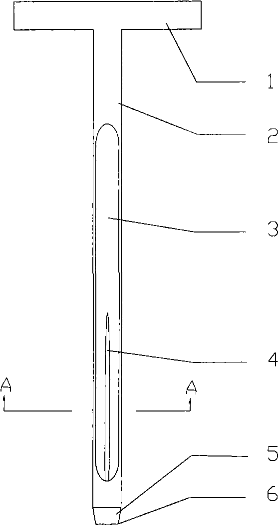
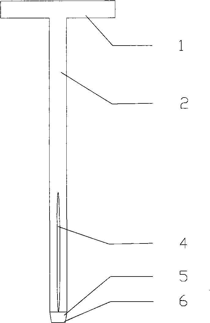
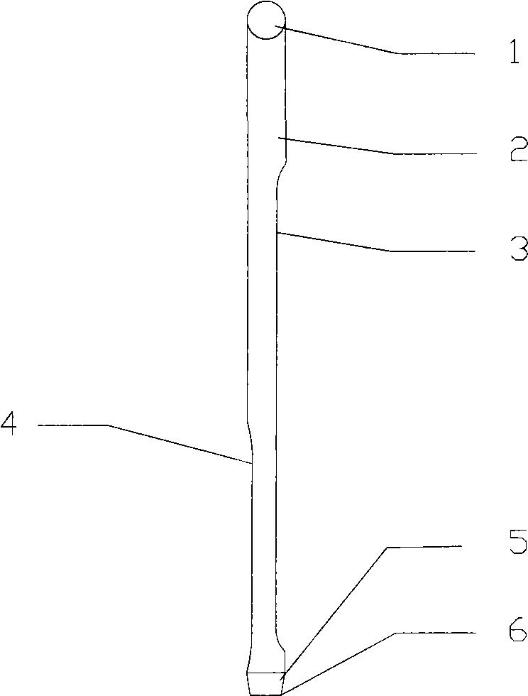
[0030] Such as Figure 1 to Figure 7 As shown, the soil sample collector of the present invention basically includes a handle 1, a drill rod 2, and a drill bit 5, one end of the drill rod 2 is connected with the handle 1, and the other end of the drill rod 2 is connected with the drill bit 5, and the drill rod 2 is connected with the drill bit 5. 2. The drill bit 5 has a hollow structure, and one side of the drill rod 2 is provided with a sample outlet 3, and the drill bit 5 is tapered.

[0031] In order to reduce the contact area between the drill pipe 2 and the soil, a labor-saving groove 4 is provided on the pipe wall on the other side of the drill pipe 2 sample outlet 3, and the labor-saving groove 4 is a The tube wall of the rod 2 is a long strip-shaped groove concaved from the outside to the inside. The groove is similar to the bleeding groove on the bayonet, that is, the shape of the groove is generally wide in the middle and pointed at both ends.

[0032] The sample o...

Embodiment 2

[0038] The structure of this embodiment is as Figure 8 Shown, except following feature, other features are identical with embodiment 1:

[0039] The outer wall of the drill rod 2 and the upper end of the labor-saving groove 4 are provided with a booster pedal 7, and the booster pedal 7 is detachably connected with the drill rod, and specifically the support seat of the booster pedal 7 can be set on the outer wall of the drill rod (in the figure Not shown), perforate on the support seat, then pin shaft (not shown) is set on the booster pedal 7, and the pin shaft is inserted in the hole on the support seat. The effect of increasing the booster pedal 7 is that when the soil quality of the soil is relatively hard, it is more difficult to press the drill pipe 2 into the soil only by the arm. Pressing into the tillage is easier. For the convenience of carrying or storage, the handle 1 and the drill pipe 2 can be connected in a movable manner, that is, corresponding holes are open...


PUM

PropertyMeasurementUnit
lengthaaaaaaaaaa
widthaaaaaaaaaa
thicknessaaaaaaaaaa

Abstract

The invention discloses a soil sample collector comprising a handle, a drill rod and a drill bit. One end of the drill rod is connected with the handle and the other end thereof is connected with the drill bit; the drill rod and the drill bit is of a hollow structure; one side of the drill rod is provided with a sample outlet and the pipe wall of the other side of the drill rod is provided with a labor-saving groove; the upper end of the labor-saving groove is provided with a boosting pedal; and the drill bit is conical. The soil sample collector has the advantages and effects that the obtained soil column can separate from the inner wall of the drill rod naturally and is easy for transferring and bagging of soil samples; when the drill rod obtains the soil column, the soil column in the drill rod is easily poured out by only turning over a sample outlet downward; the handle, the drill rod and the boosting pedal are of a detachable-connected structure, thus being convenient to carry and store and having small occupied space; the boosting pedal can lead the hand and foot to apply force simultaneously; the soil sample collector is shorter in whole, smooth and portable, is easy to generate force, has small resistance, high working efficiency, simple technique, convenient material-obtaining and low cost and is convenient for promotion and application.

Description

technical field [0001] The invention relates to agricultural machinery, in particular to a soil sample collector. Background technique [0002] In agricultural production practice and scientific research, it is often necessary to collect plow layer soil (topsoil layer 0-20 cm thick) for nutrient status analysis or environmental quality assessment. The collection of soil samples follows the principles of randomness and representativeness, and multi-point and full-plow layer sampling is particularly important, which requires that the full-plow layer be uniformly collected and mixed at as many points as possible to represent a field or an area tillage soil. Therefore, quick, convenient and large-scale multi-point soil extraction from the plow layer in a short period of time has always been the goal pursued by soil workers. At present, there are mainly two methods for soil sampling in the plow layer, one with a hoe, and the other with a soil fetcher. The former has low effici...

Claims


Application Information

Patent Timeline
Patent Type & Authority Applications(China)
IPC IPC(8): G01N1/08
Inventor 姚建武艾绍英李盟军王艳红曾招兵唐明灯
Owner 广东省农业科学院土壤肥料研究所
Why Eureka
Try Eureka