Decorative lamp based on magnetic coupling resonance type wireless energy transmission technology

A wireless energy transmission and resonant technology, which is applied in the direction of lighting devices, lamp circuit layout, lighting device components, etc., can solve problems such as placement restrictions

Inactive Publication Date: 2009-08-19
HARBIN INST OF TECH
View PDF0 Cites 7 Cited by
  • Summary
  • Abstract
  • Description
  • Claims
  • Application Information

AI Technical Summary

Problems solved by technology

[0003] The present invention aims to solve the problem that the existing decorative lamps need to be connected by wires, resulting in restricted placement, thus proposing a decorative lamp based on magnetic coupling resonant wireless energy transmission technology

Method used


Image

  • Decorative lamp based on magnetic coupling resonance type wireless energy transmission technology
  • Decorative lamp based on magnetic coupling resonance type wireless energy transmission technology

Examples


specific Embodiment approach 1

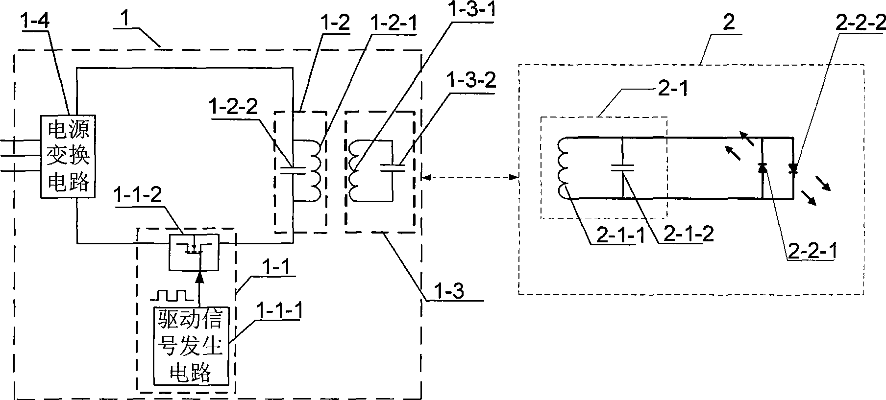
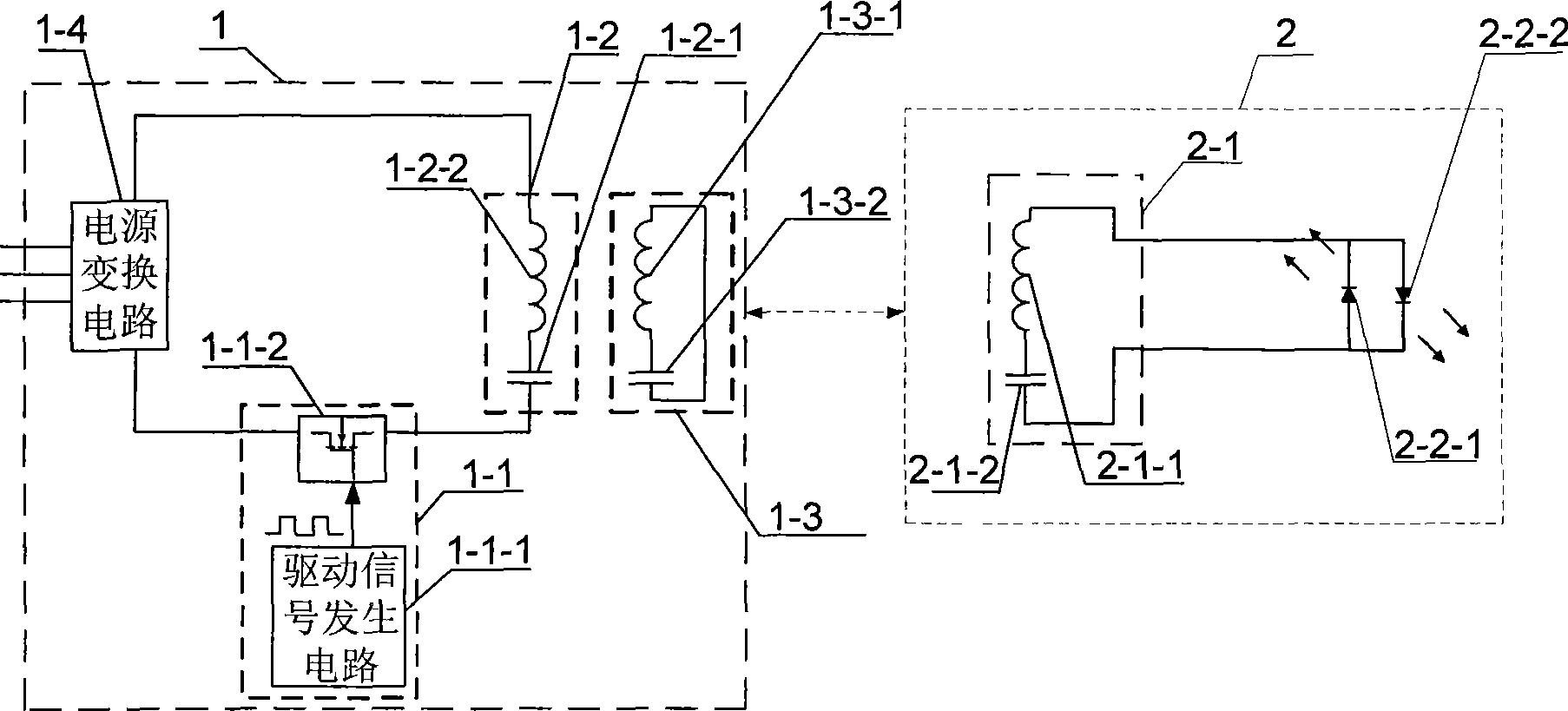
[0007] Specific implementation mode one: combine figure 1 and figure 2 Describe this embodiment, the decorative lamp based on the magnetic coupling resonant wireless energy transmission technology, it includes the emission source 1 with booster, the emission source 1 with booster is excited by magnetic field resonance and drive circuit 1-1, resonant The transmitting circuit 1-2, the booster 1-3 and the power conversion circuit 1-4 are composed; the magnetic field resonance excitation and driving circuit 1-1 is composed of the driving signal generating circuit 1-1-1 and the driving switch tube 1-1-2, It is used to supplement the energy of the DC power supply to the resonant transmitting circuit 1-2; the resonant transmitting circuit 1-2 is composed of a resonant transmitting coil 1-2-1 and a resonant transmitting capacitor 1-2-2 connected in parallel or in series, and is used to send energy to The booster 1-3, the booster 1-3 is composed of a resonance booster coil 1-3-1 and ...

specific Embodiment approach 2

[0008] Embodiment 2: The difference between this embodiment and the decorative lamp based on magnetic coupling resonance wireless energy transmission technology described in Embodiment 1 is that the decorative lamp 2 with a resonant receiving circuit also includes a second light-emitting diode 2- 2-2, the anode of the second light emitting diode 2-2-2 is connected to the cathode of the first light emitting diode 2-2-1, and the cathode of the second light emitting diode 2-2-2 is connected to the first light emitting diode 2-2 The positive connection of -1.

[0009] Working principle: the enhanced emission source 1 of the present invention is composed of a magnetic field resonance excitation and drive circuit 1-1, a resonant emission circuit 1-2, an intensifier 1-3 and a power conversion circuit 1-4;

[0010] The magnetic field resonance excitation and drive circuit 1-1 is composed of a drive signal generation circuit 1-1-1 and a drive switch tube 1-1-2. The drive signal generat...

specific Embodiment approach 3

[0015] Specific embodiment three: The difference between this specific embodiment and the decorative lamp based on magnetic coupling resonance wireless energy transmission technology described in specific embodiment two is that the first light-emitting diode 2 in each decorative lamp 2 with a resonant receiving circuit- Both 2-1 and the second light emitting diode 2-2-2 are colored light emitting diodes.


PUM


Abstract

The invention provides a decorating lamp based on magnetic coupling resonant mode wireless energy transmitting technique. The lamp solves problem of put limitation caused by the present decorating lamp needing a lead wire connection. The decorating lamp is composed of a resonant receiving loop, a resonant receiving capacitance and a first, a second LBD, the resonant receiving loop and the resonant receiving capacitance are connected in parallel or in series, an cathode of a first LBD connects with an anode of the second LBD, then connects with one end of the resonant receiving capacitance, the anode of the first LBD connects with the cathode of the second LBD, then connects with another end of the resonant receiving capacitance, the decorating lamp locates in an emitter region of an emitter source with an enhancer, the decorating lamp amount is at least one. The decorating lamp is suitable for multi-location need the decorating lamp, such as Christmas tree.

Description

technical field [0001] The invention relates to a decorative lamp, in particular to a decorative lamp based on magnetic coupling resonance wireless energy transmission technology. Background technique [0002] The existing decorative lamps are all connected in series or in parallel with wires and connected to the 220V power supply. The disadvantage is that the position of each decorative lamp cannot be placed as desired due to the existence of wires. . Contents of the invention [0003] The purpose of the present invention is to solve the problem that the existing decorative lamps need to be connected by wires, resulting in restricted placement, thus proposing a decorative lamp based on magnetic coupling resonance wireless energy transmission technology. [0004] A decorative lamp based on magnetic coupling resonance wireless energy transmission technology, which includes a radiation source with a booster, and the radiation source with a booster is composed of a magnetic ...

Claims


Application Information

Patent Timeline
Patent Type & Authority Applications(China)
IPC IPC(8): H05B37/00F21V23/00F21Y101/02F21Y115/10
Inventor 逯仁贵于志毛银花裴磊于春来任立涛张小壮朱春波陈伟
Owner HARBIN INST OF TECH
Why Eureka
Try Eureka