Cooled turbine rotor blade

A turbine and cooling technology, applied in the direction of blade support components, mechanical equipment, engine functions, etc., can solve the problems of overheating in the reversing area, reduce the life of turbine blades, etc., and achieve the effect of improving accuracy

Inactive Publication Date: 2009-08-19
SIEMENS AG
View PDF3 Cites 9 Cited by
  • Summary
  • Abstract
  • Description
  • Claims
  • Application Information

AI Technical Summary

Problems solved by technology

Despite the use of commutator segments, local overheating can also occur in the commutation area, which reduces the life of the turbine blades

Method used


Image

  • Cooled turbine rotor blade

Examples


Embodiment Construction

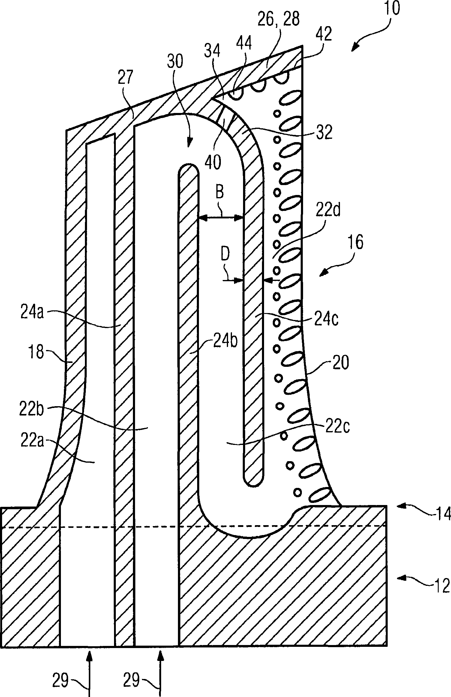
[0014] The drawing shows a turbine rotor blade 10 produced by casting in a longitudinal section. The integral turbine rotor blade 10 thus has a fir-tree-shaped fastening region 12 in cross section, which has a platform 14 and an airfoil profile 16 arranged thereon. The aerodynamically shaped airfoil profile 16 in cross section is formed by a suction-side blade wall and a pressure-side blade wall, which each extend from the leading edge 18 to the trailing edge 20 and in this case surround the A cavity arranged inside the airfoil profile 16 in which a plurality of cooling channels 22a, 22b, 22c, 22d are arranged. The cooling channels 22 adjoin each other and each run approximately parallel to the front edge 18 . The mutually adjoining cooling channels 22 are each separated from one another in sections by ribs 24 a , 24 b , 24 c connecting the pressure-side blade wall and the suction-side blade wall. In the region of the wing tip 27 lying opposite the fastening region 12 , the ...


PUM


Abstract

The invention specifies a turbine rotor blade (10) for a gas turbine which is traversed axially by flow, which turbine rotor blade (10) is equipped with a fastening region (12) and an aerofoil profile (16). Meandering cooling ducts (22b, 22c, 22d) with interposed deflecting regions (30) are provided in the interior of the aerofoil profile (16). In the deflecting regions (30), it is possible to prevent dead water regions, which are generated in the prior art, by virtue of at least one of the fins (24) running so as to curve towards the front edge (18) or towards the rear edge (20) in the region of the aerofoil tip (27). At the same time, an opening (40) is provided in the curvature (32) of the fin (24), through which opening (40) a part of the coolant (29) which flows in the deflecting region (30) can pass over into the adjacent cooling duct (24).

Description

technical field [0001] The invention relates to a cooled turbine rotor blade according to the preamble of claim 1 . Background technique [0002] Such a turbine rotor blade with an airfoil profile is known, for example, from EP 0 735 240 A1. For the cooling of the airfoil profile, a plurality of adjacent cooling channels are provided inside, which can be arranged in a meandering manner through which a cooling medium flows continuously. The cooling channels here each run parallel to the front edge. In each case adjacent cooling channels are separated from one another by ribs, the ribs terminating in a deflection region in which adjacent cooling channels transition into one another. In order to avoid regions with a low flow velocity and therefore insufficient cooling in this deflection region, in which eg cooling air is deflected from an outward flow to an inward flow, a commutation segment ( Figure 12). Despite the use of the commutator segments, localized overheating can...

Claims


Application Information

Patent Timeline
Patent Type & Authority Applications(China)
IPC IPC(8): F01D5/18F01D25/12
CPCF05D2260/2212F05B2260/202F05D2240/122F05D2250/185F05D2240/304F05D2260/202Y02T50/673Y02T50/676F01D5/187F05B2260/222Y02T50/60
Inventor H·-J·格罗斯
Owner SIEMENS AG
Why Eureka
Try Eureka