Plate heat exchanger and heat exchanger plant

A technology of plate heat exchangers and heat exchangers, applied in heat exchange equipment, lighting and heating equipment, heat exchange equipment safety devices, etc., can solve the problems of serious quantity and performance reduction of plate heat exchangers

Inactive Publication Date: 2009-08-19
ALFA LAVAL CORP AB
View PDF1 Cites 4 Cited by
  • Summary
  • Abstract
  • Description
  • Claims
  • Application Information

AI Technical Summary

Problems solved by technology

Accumulated oil continuously degrades the performance of the plate heat exchanger

Method used


Image

  • Plate heat exchanger and heat exchanger plant
  • Plate heat exchanger and heat exchanger plant
  • Plate heat exchanger and heat exchanger plant

Examples


Example Embodiment

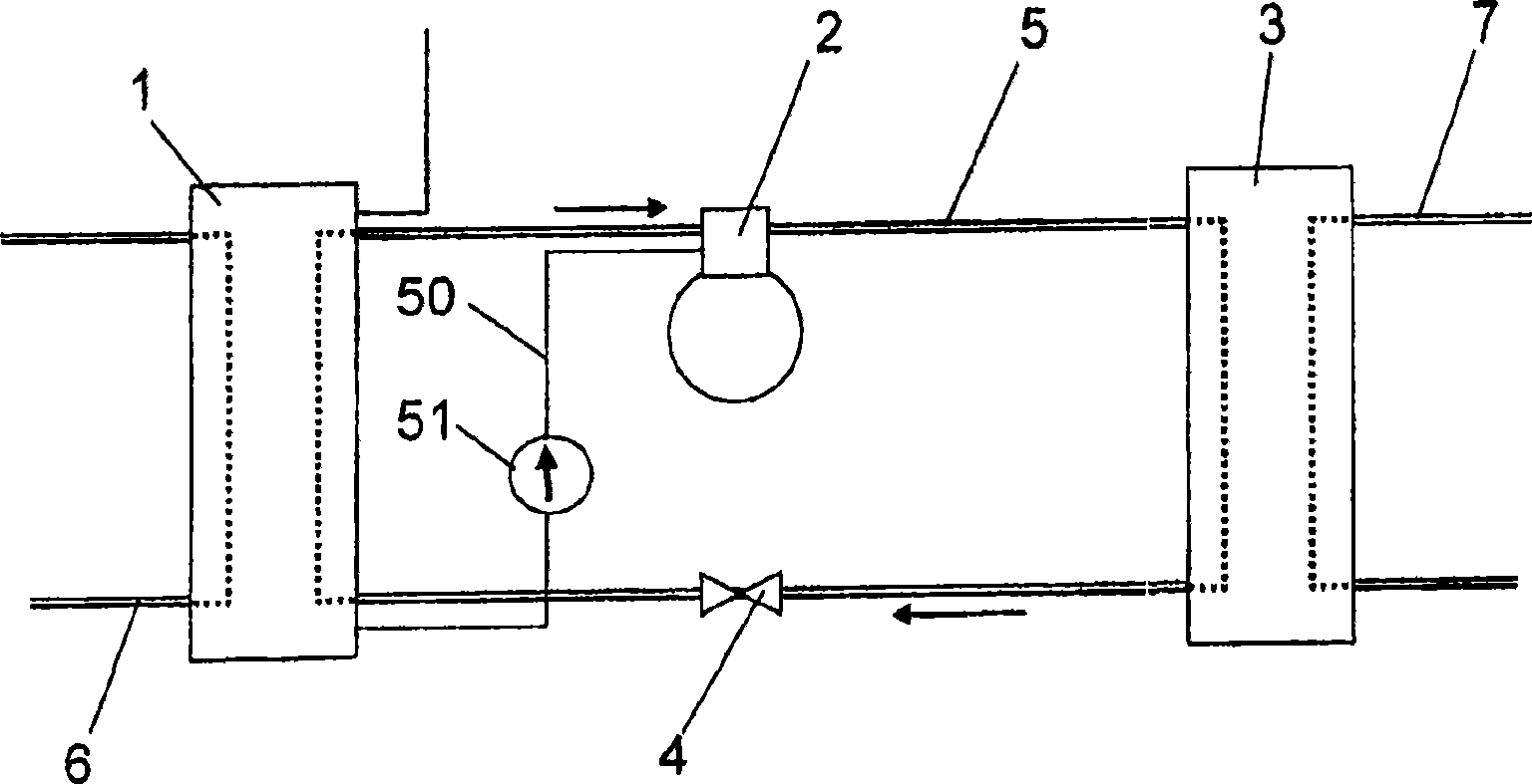
[0031] figure 1 A heat exchanger apparatus comprising an evaporator 1, a compressor 2, a condenser 3 and an expansion element 4 is disclosed. The evaporator 1 , the compressor 2 , the condenser 3 and the expansion element 4 are connected to each other by a cooling medium pipe 5 and form a closed cooling medium circuit through which the first medium circulates. In the disclosed embodiments, the first media all include or consist of ammonium as a major component. The present invention is also applicable to other cooling media than ammonium, such as different types of Freon. A second medium for heating the cooling medium is also supplied to the evaporator 1 via the external circuit 6 . The condenser 3 is also connected to an external circuit 7 for supplying a third medium of cooling cooling medium.

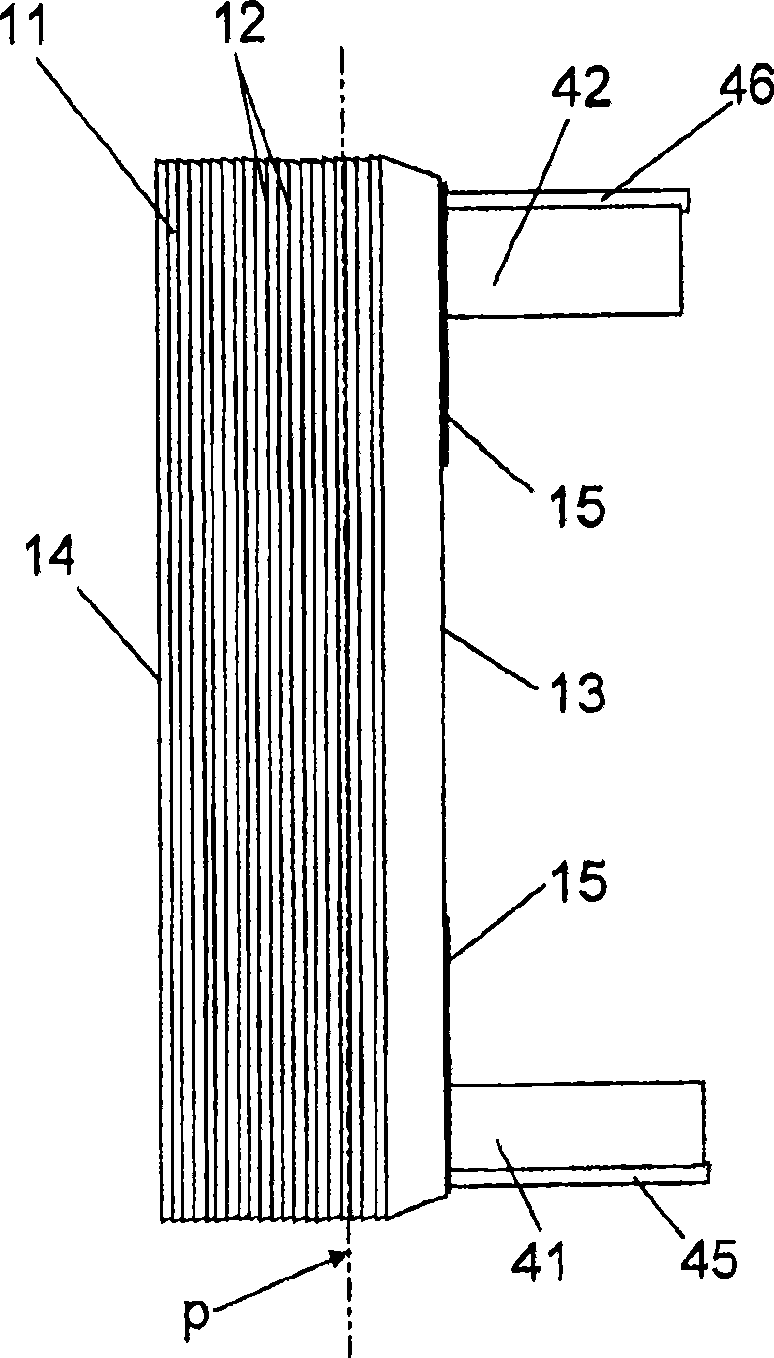
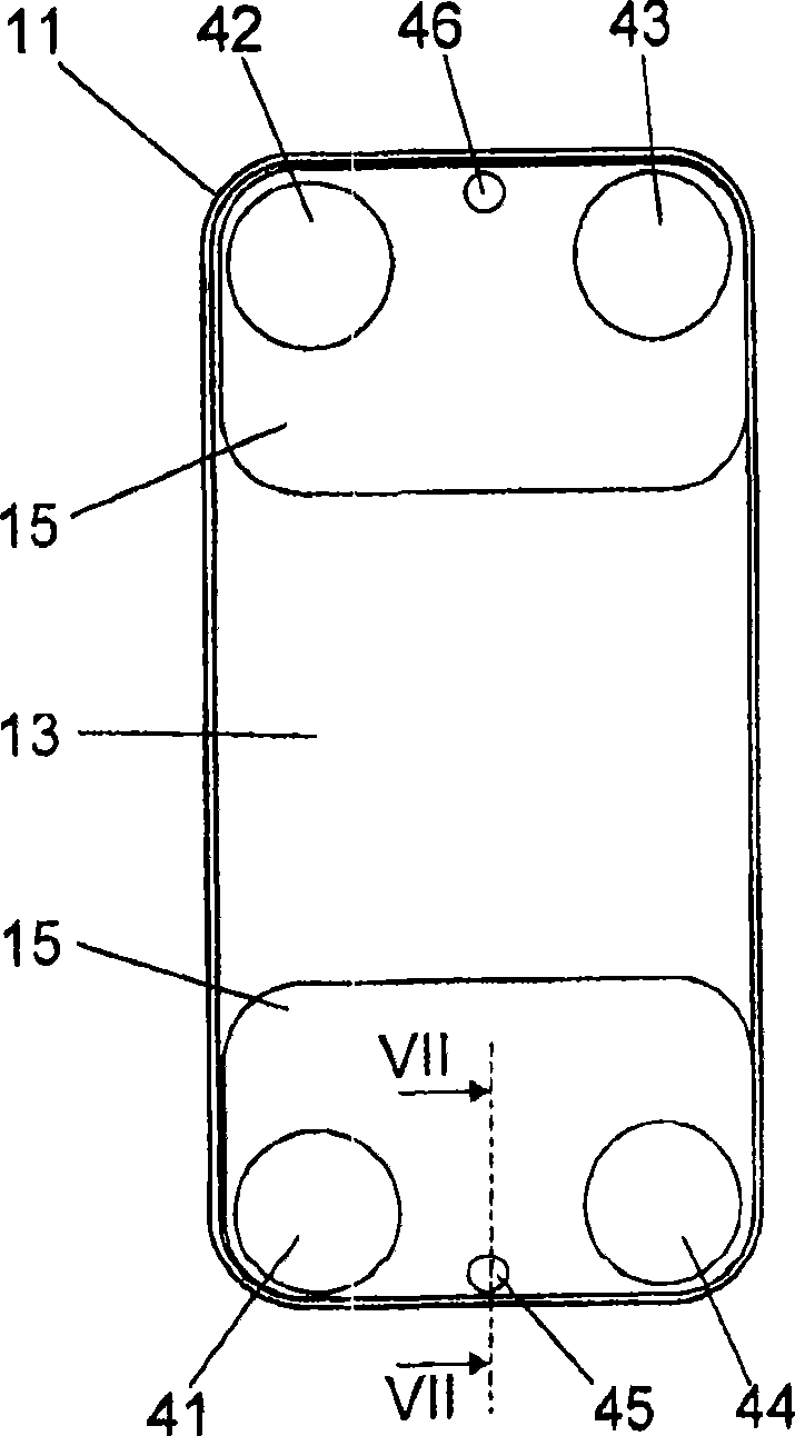
[0032] Next, in one embodiment, the plate heat exchanger will be explained further, where the plate heat exchanger is used as an evaporator. It should be noted, however, that a pla...


PUM


Abstract

The invention refers to a heat exchanger plant and a plate heat exchanger. The plate heat exchanger comprises a plate package (11) having heat exchanger plates provided beside each other for forming first plate interspaces for a first medium to be evaporated and second plate interspaces for a second medium in an alternating order in the plate package. Each heat exchanger plate comprises four portholes forming a first inlet port, which communicates with the first plate interspaces for supply of the first medium, a first outlet port, which communicates with the first plate interspaces for discharge of the first medium, a second inlet port, which communicates with the second plate interspaces for supply of the second medium, and a second outlet port, which communicates with the second plate interspaces for discharge of the second medium. The plate package comprises a drainage port (45), which communicates with the first plate interspaces and is closed in relation to the second plate interspaces. The drainage port permits discharge of a fluid collected in the first plate interspaces.

Description

technical field [0001] The invention relates to a plate heat exchanger according to the preamble of claim 1 and a heat exchanger arrangement according to the preamble of claim 20 . Background technique [0002] Such a plate heat exchanger in the form of an evaporator and / or a condenser can form part of a cooling medium circuit which also includes a compressor, a condenser, an expansion valve and an evaporator. The first medium is a cooling medium, such as ammonium, circulating through the components of the cooling medium circuit, and the second medium is a heat transfer medium, which can be any medium that can be cooled, such as water, oil, etc. During operation of this plate heat exchanger with a cooling medium in which oil is insoluble, such as ammonium, oil is collected in the plate heat exchanger, more precisely in the first plate gap. The oil is mainly emitted from the lubrication of the compressor in the ammonium circuit. Accumulated oil continuously degrades the per...

Claims


Application Information

Patent Timeline
IPC IPC(8): F25B39/02F25B41/00F25B31/00B01D1/22F28D9/00F28F3/08
CPCF28D9/005F28D2021/0061F28F2265/06F25B39/00F28B9/10F28D2021/0071F28F17/005F28D2021/007F28D2021/0064F28F2225/00F28F2265/18
Inventor R·埃克伦C·斯滕赫德P·比约恩森
Owner ALFA LAVAL CORP AB
Why Eureka
Try Eureka