

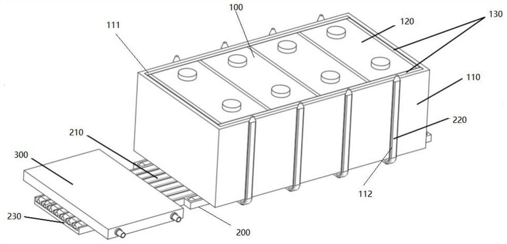
Power battery module cooling system
A technology of heat dissipation system and power battery, applied in secondary batteries, circuits, electrical components, etc., can solve the problems affecting the surface temperature uniformity of power battery modules, overheating, and high heat dissipation energy consumption
- Summary
- Abstract
- Description
- Claims
- Application Information
AI Technical Summary
Problems solved by technology
Method used
Image

Examples
Embodiment 1
[0044] Under the 1C discharge rate of the battery module 100, the heat dissipation effect of the battery surface between the present invention and the traditional bottom water-cooled heat dissipation method is studied. The battery module with a penetrating water-cooled plate installed at the bottom is used as a blank control group, and the power battery module of the present invention is used to dissipate heat. system as the experimental group.
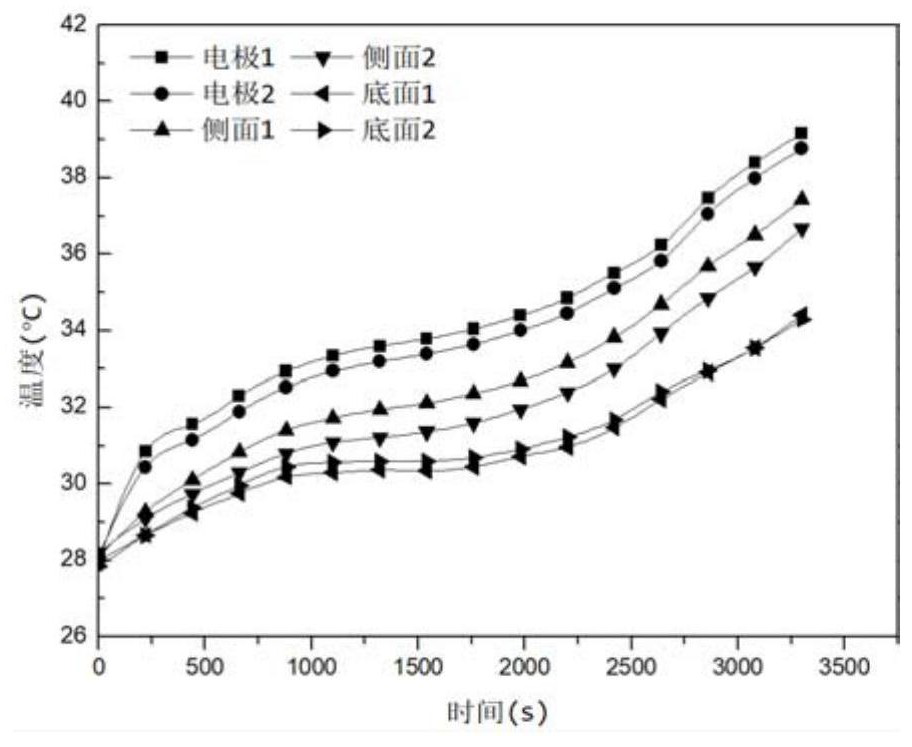
[0045] The battery module 100 has a capacity of 120Ah, and the ambient temperature during the test is 28°C. A constant temperature water tank is used to continuously supply cooling water at a temperature of 25°C to the bottom water cooling block, and the water flow rate is 100L / h. During the test, six temperature measurement points were arranged on the surface of the battery module 100 . Wherein, there are two electrodes, one side surface and two bottom surfaces respectively.
[0046] Such as image 3 As shown, under the traditional...
Embodiment 2
[0049] Under the discharge rate of 1C of the battery module 100, the battery surface heat dissipation effect of the power battery module heat dissipation system of the present invention and the traditional bottom water cooling heat dissipation method is studied. The battery module with the water-cooled plate installed at the bottom is used as the blank control group, and the heat dissipation system of the battery module using the semiconductor cooling sheet composite water cooling block is used as the experimental group. section, the heating surface is attached to the surface of the water cooling block through the heat conduction layer. Use a constant temperature water tank to continuously feed cooling water with a water temperature of 25°C into the bottom water cooling block, and the water flow rate is 100L / H.
[0050] Such as Figure 5 As shown, the heat dissipation method using semiconductor refrigeration sheet composite water cooling block in the condensation section of t...
PUM
 Abstract
Description
Claims
Application Information