Rotor cooling for a dynamoelectrical machine

A technology for rotors and cooling holes, applied to the rotating parts of the magnetic circuit, the shape/style/structure of the winding conductor, the shape/style/structure of the magnetic circuit, etc., can solve the problems of radial channel shunting difficulties, and achieve simple manufacturing, The effect of cost reduction

Active Publication Date: 2009-08-19
西门子能源全球两合公司
View PDF0 Cites 7 Cited by
  • Summary
  • Abstract
  • Description
  • Claims
  • Application Information

AI Technical Summary

Problems solved by technology

Difficulty diverting flow into the radial channels due to high flow velocities in the base channels on the rotor end face
This results in a poor onward flow of the cooling medium into the radial channels on the rotor face

Method used


Image

  • Rotor cooling for a dynamoelectrical machine
  • Rotor cooling for a dynamoelectrical machine
  • Rotor cooling for a dynamoelectrical machine

Examples


Embodiment Construction

[0026] Embodiment of the invention

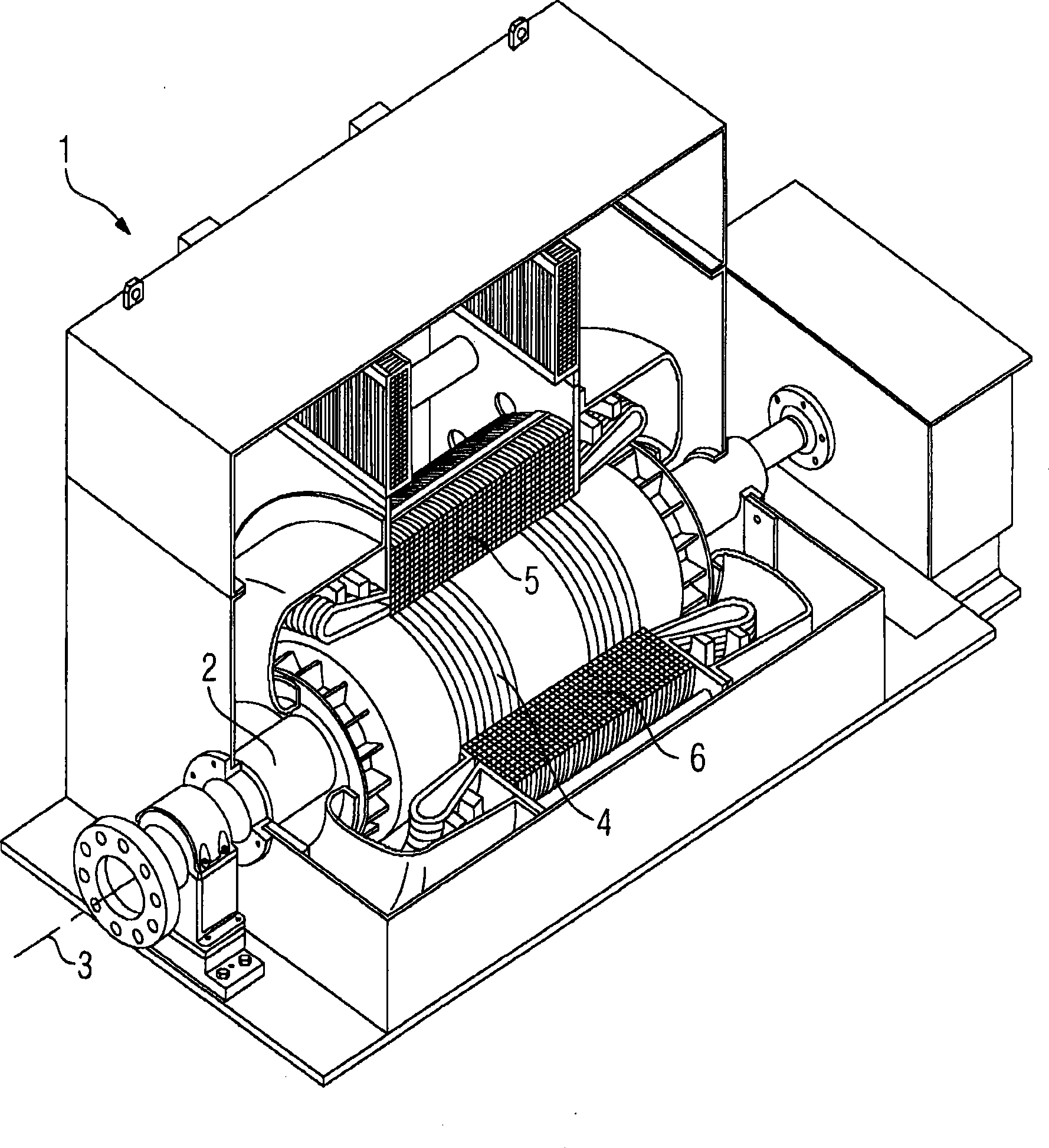
[0027] exist figure 1 A perspective view of a generator 1 can be seen in . The generator 1 is to be regarded as an embodiment of an electric machine. Another example of an electrical machine could be an electric motor. The generator 1 basically has two components. The rotor 2 is arranged rotatably about an axis of rotation 3 . The rotor 2 has a plurality of axially oriented conductors 4 . The electrical conductor 4 is supplied with an excitation current via an excitation current supply (not further shown). This produces a magnetic field surrounding the rotor 2 . The rotor 2 is set in rotation by a steam or gas turbine (not shown). The rotational frequency here is generally at 50 or 60 Hz.

[0028] Arranged around the rotor 2 is a stator 5 which has a stator winding 6 . A voltage is induced in the stator winding 6 by the rotating magnetic field of the rotor 2 and is then fed into the high-voltage network. The exciting current flo...


PUM


Abstract

The invention relates to a rotor (2) for a dynamoelectric machine. A bottom duct (9), through which a cooling medium flows and the conductors (4) are cooled via radial ducts (12) during operation, is disposed in the rotor (2). According to the invention, the bottom duct (9) is embodied such that the cross section thereof decreases towards the center of the rotor (2).

Description

technical field [0001] The invention relates to a rotor for an electric machine, wherein the rotor has base channels for cooling conductors arranged on the rotor, wherein the rotor is designed such that a cooling medium can flow through the rotor during operation. Background technique [0002] An electrical machine is to be understood as a generator or an electric motor. The present application relates preferably to electrical generators, wherein the invention can also be applied to other electrical machines. Generators for regional energy supply have a power capacity of several hundred MVA. A generator basically has a rotor and a stator arranged around the rotor. Both the rotor and the stator have conductors through which current flows. This current is relatively high and causes intense heating of the conductor. Therefore the conductors, especially in the rotor, must be cooled. Basically, two cooling media are used or used for this purpose. For example, hydrogen or wa...

Claims


Application Information

Patent Timeline
Patent Type & Authority Applications(China)
IPC IPC(8): H02K1/32H02K3/24
CPCH02K3/24H02K1/32
Inventor H·阿多尔夫H·卡卢扎O·米切尔森J·赖诺尔德
Owner 西门子能源全球两合公司
Why Eureka
Try Eureka