Eureka AIR delivers breakthrough ideas for toughest innovation challenges, trusted by R&D personnel around the world.

Deformable aerofoil

A wing, diamond-shaped technology, applied in the aerospace field, can solve the problems of low flight efficiency, poor air tightness, and complex structure of aircraft, and achieve the effects of improving flight efficiency, simple structure, and reducing the quality of the wing.

Active Publication Date: 2009-08-26
HARBIN INST OF TECH
View PDF0 Cites 20 Cited by
  • Summary
  • Abstract
  • Description
  • Claims
  • Application Information

AI Technical Summary

Problems solved by technology

[0004] The purpose of the present invention is to solve the problems of complex structure, large mass, low flight efficiency and poor airtightness of existing deformable aircraft wings, and to provide a deformable wing

Method used


Image

  • Deformable aerofoil
  • Deformable aerofoil
  • Deformable aerofoil

Examples


specific Embodiment approach 1

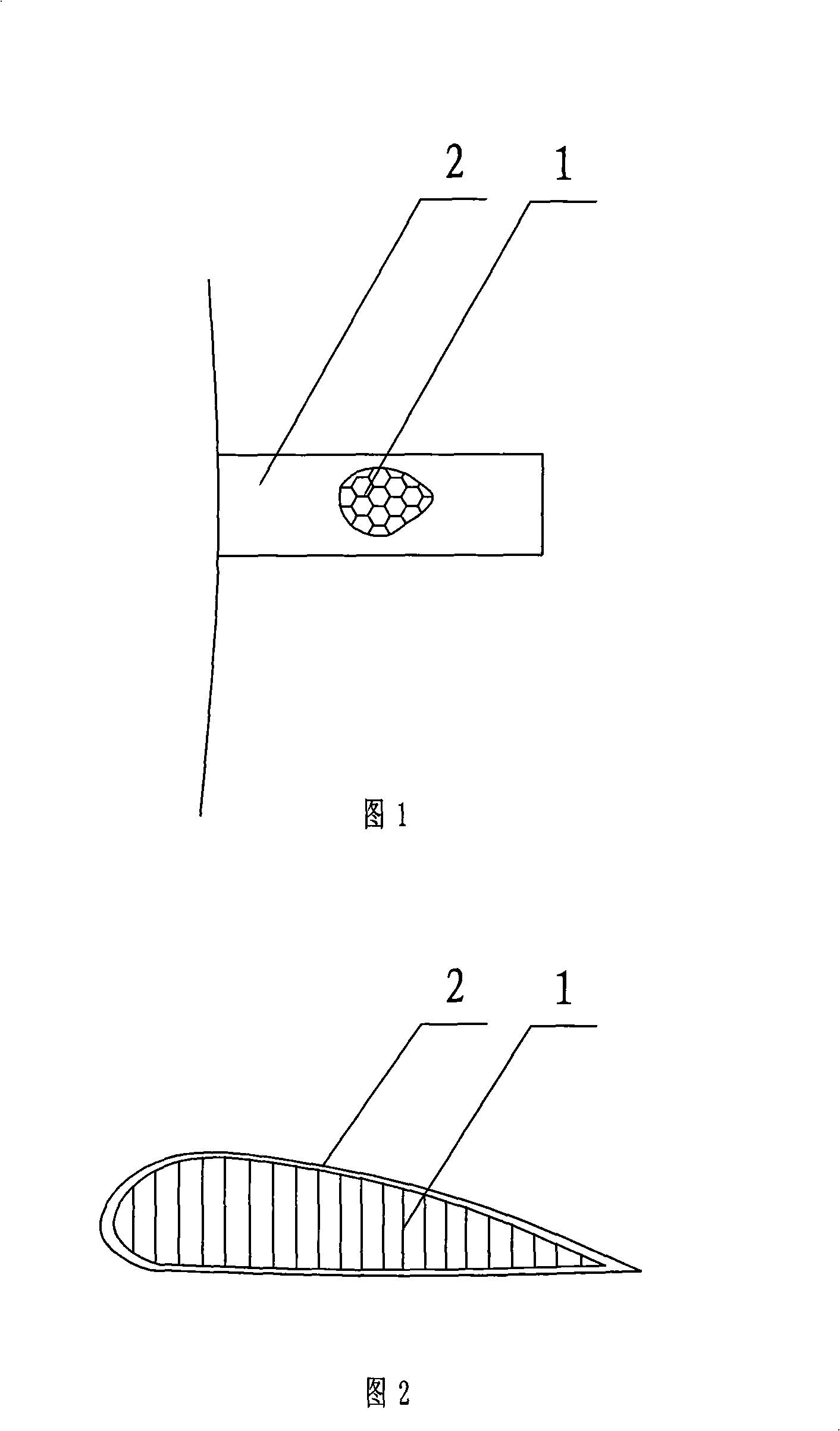
[0008] Specific implementation mode one: combine Figure 1 ~ Figure 2 Describe this embodiment, a kind of deformable wing of this embodiment is made up of honeycomb sandwich matrix 1 and skin 2, and described honeycomb sandwich matrix 1 is the honeycomb structure body of the prefabricated wing shape of one body, and described skin 2 Wrapped on the outer surface of the honeycomb sandwich matrix 1.

specific Embodiment approach 2

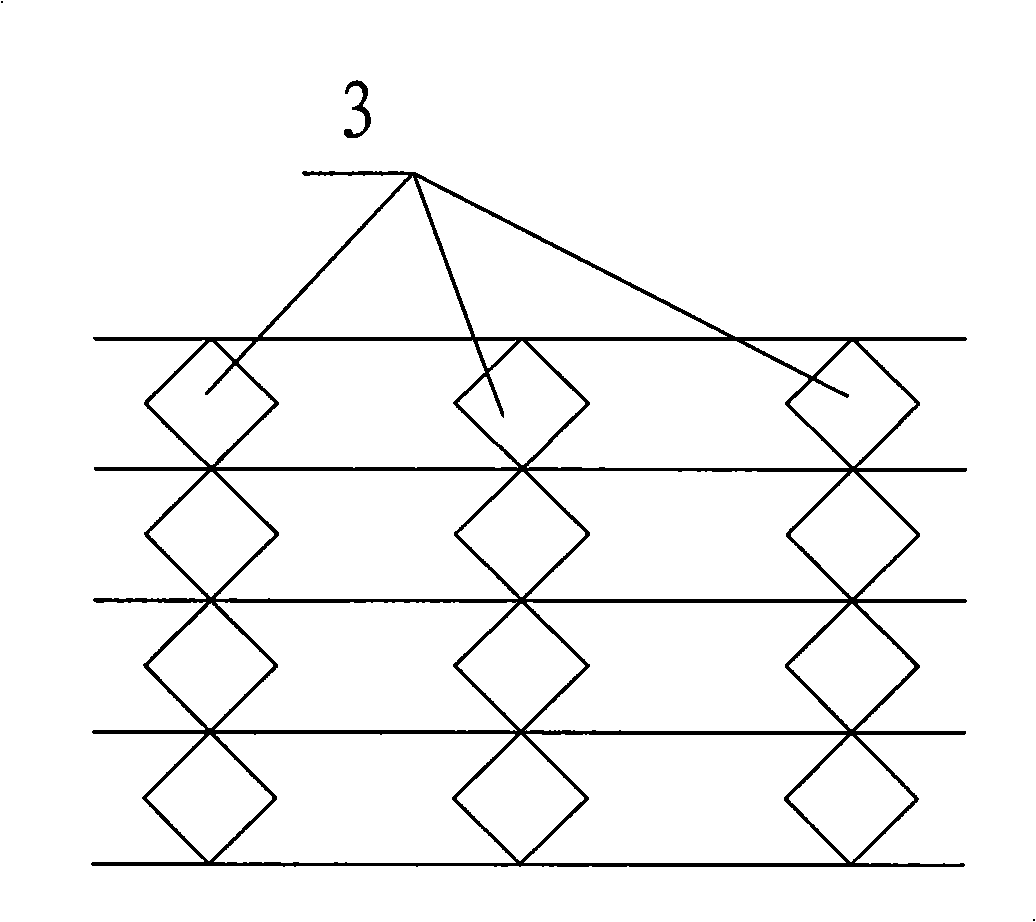
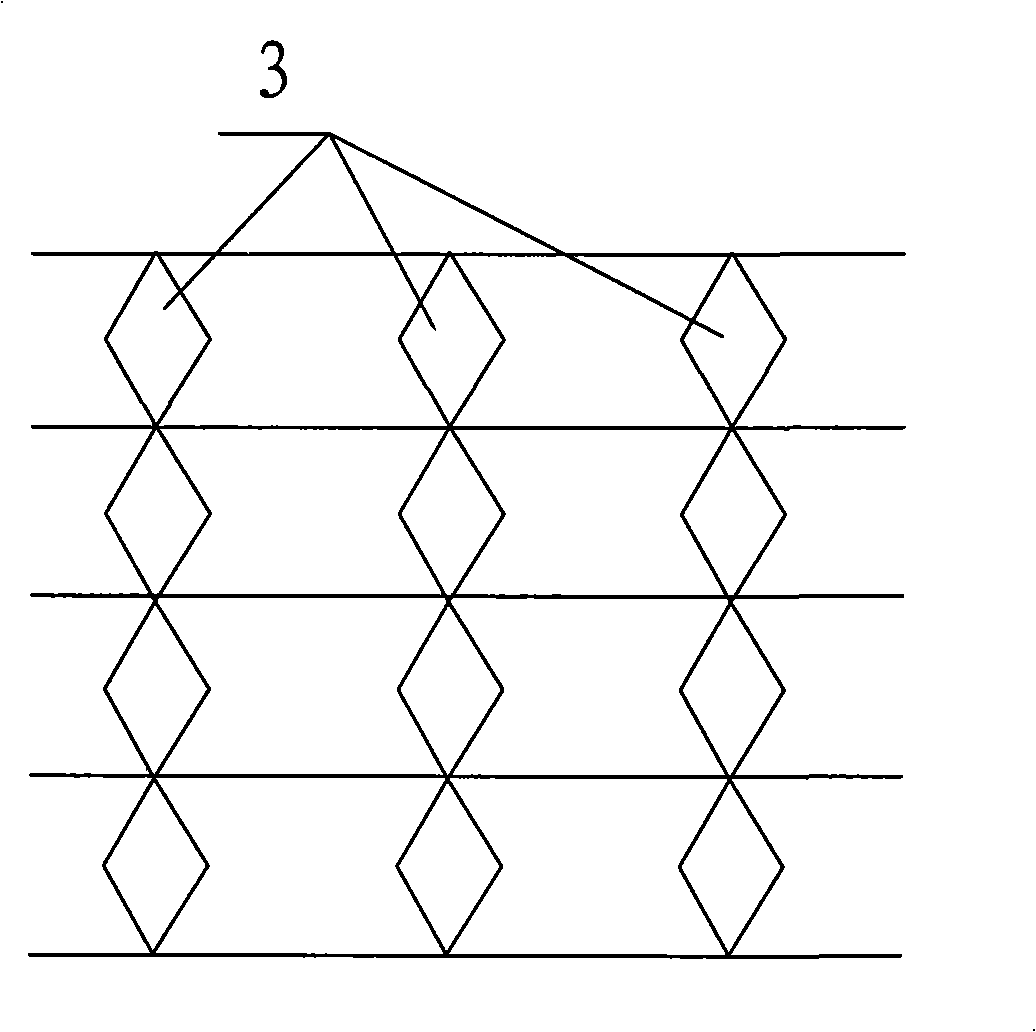
[0009] Specific implementation mode two: combination Figure 3 ~ Figure 4 with Figure 13 ~ Figure 14 Describe this embodiment, the honeycomb interlayer matrix 1 of this embodiment is the honeycomb structure body that unidirectional Poisson's ratio is zero, the cross-sectional shape of the honeycomb 3 of the honeycomb interlayer matrix 1 is rhombus, the honeycomb 3 of the honeycomb interlayer matrix 1 is in Continuous distribution in the vertical direction and interval distribution in the horizontal direction. Such arrangement satisfies the requirement of stretching or compressing in the vertical direction without causing deformation in the horizontal direction, and realizes deformation in the direction of the span of the wing or in the direction of the chord length. Other components and connections are the same as those in the first embodiment.

specific Embodiment approach 3

[0010] Specific implementation mode three: combination Figure 5 ~ Figure 6 with Figure 13 ~ Figure 14 Describe this embodiment, the honeycomb sandwich matrix 1 of this embodiment is the honeycomb structure body that unidirectional Poisson's ratio is zero, the cross-sectional shape of the honeycomb 3 of the honeycomb sandwich matrix 1 is semicircular, the honeycomb of the honeycomb sandwich matrix 1 3 are distributed continuously in the vertical direction and discontinuously distributed in the horizontal direction, the two honeycombs 3 that are continuous in the vertical direction have opposite protrusion directions, and the two honeycombs 3 that are intermittent in the horizontal direction have the same protrusion direction. Such arrangement satisfies the requirement of stretching or compressing in the vertical direction without causing deformation in the horizontal direction, and realizes deformation in the direction of the span of the wing or in the direction of the chord ...


PUM


Abstract

The invention relates to a deformable aerofoil, which solves the problems of complex structure, and large mass of the aerofoil of the existing deformable aircraft and the problems of low flying efficiency and poor air-tightness of the aircraft. The invention consists of a honeycomb sandwich matrix (1) and a cover (2); the honeycomb sandwich matrix (1) is an integral honeycomb structure of a prefabricated aerofoil shape; the cover (2) is coated on the outer surface of the honeycomb sandwich matrix (1). The aerofoil of the invention employs the honeycomb sandwich structure which has higher specific strength and specific rigidity, corrosion and fatigue resistance, excellent electric insulating performance and electromagnetic wave transmission characteristic. The honeycomb sandwich structure greatly reduces the mass of the aerofoil, and improves the flying efficiency of the aircraft. The integral honeycomb structure of a prefabricated aerofoil shape of the honeycomb sandwich matrix leads the aircraft to have better air-tightness and is a simple. The design of the honeycomb sandwich structure leads the aerofoil to be suitable for various shape changes.

Description

technical field [0001] The invention relates to a deformable wing and belongs to the technical field of aerospace. Background technique [0002] Wings are a major component in aircraft design. The geometric shape of the conventional wing is designed according to the specific task, specific altitude, Mach number and aircraft weight. For example, high lift-to-drag ratio and large wing area are required during cruise; high lift coefficient and large wing area are required during take-off and landing. Wing area; large sweep angle and small aspect ratio for high speed flight and maneuvering. Usually, only one design point is optimal for a fixed-wing wing. The flight parameters change continuously during flight, and the geometric shape of the wing is not optimal in most cases. How to make the shape of the aircraft adapt to various flight states and have the best aerodynamic characteristics in the entire flight envelope has become the development direction of today's and future a...

Claims


Application Information

Patent Timeline
IPC IPC(8): B64C3/00B64C3/20B64C3/26
Inventor 冷劲松刘彦菊孙健
Owner HARBIN INST OF TECH
Why Eureka
Eureka Blog
Learn More