Dissipative element of grouting sleeve

A technology of energy-consuming components and casings, which is applied to building components, shock-proof and other directions, can solve the problems of restricting the wide application of energy-consuming supports, high processing accuracy requirements, inconvenient maintenance and replacement, etc., and achieves simple construction, low cost, and easy installation. Effect

Active Publication Date: 2009-08-26
TONGJI UNIV
View PDF0 Cites 15 Cited by
  • Summary
  • Abstract
  • Description
  • Claims
  • Application Information

AI Technical Summary

Problems solved by technology

The existing energy-dissipating support adopts the method of installing various energy-dissipating elements and damping devices with different functions on the ordinary support or using large-ductile metal materials, which...

Method used


Image

  • Dissipative element of grouting sleeve
  • Dissipative element of grouting sleeve

Examples


Embodiment Construction

[0016] The preferred embodiments of the invention will be described in detail below in conjunction with the accompanying drawings.

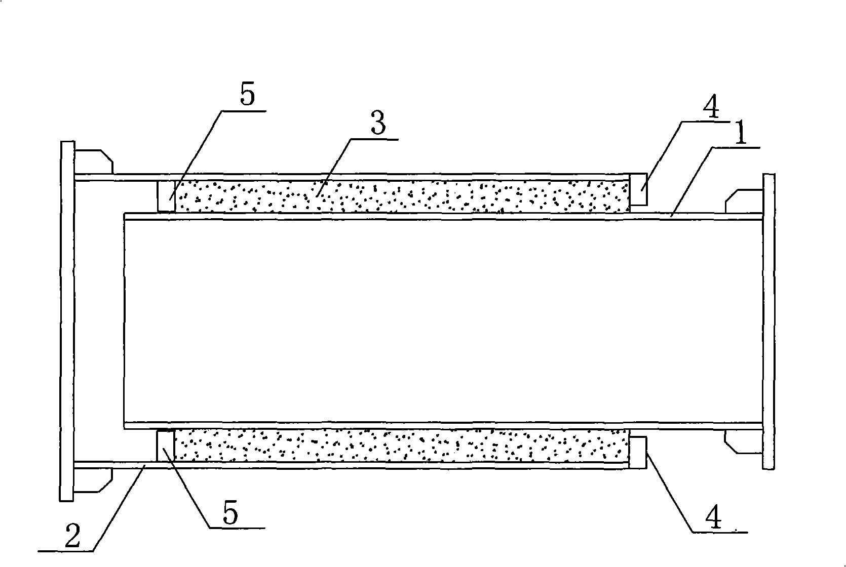
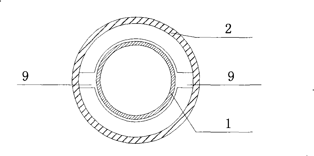
[0017] like figure 1 As shown, as an embodiment of the present invention, the energy-dissipating element of the grouting casing includes an inner pipe 1 and an outer pipe 2, the inner pipe 1 is inserted into the outer pipe 2 along the pipe axis and overlapped coaxially, the outer wall of the inner pipe 1 and the outer The surface of the inner wall of the pipe 2 can be sandblasted or shot blasted. The outer end of the overlapping section of the outer pipe 2 and the inner pipe 1 is provided with an annular outer ring plate 4, and the inner end of the overlapping section of the outer pipe 2 and the inner pipe 1 is provided with a Annular inner ring plate 5 (such as figure 2 shown), the outer ring plate 4 and the inner ring plate 5 are only fixedly connected with the outer pipe 2, and the inner ring plate 5, the outer ring plate 4, the inner pipe 1...


PUM


Abstract

The invention discloses a dissipative element of a grouting sleeve, comprising an inner tube and an outer tube which are arranged coaxially. The slit between the lap sections of the outer tube and the inner tube is provided with expanding cement slurry, and an expanding cement sheath is formed after the expanding cement slurry is cured. The pretension force of the expanding cement slurry enables the friction force of the contact surface between the expanding cement sheath and the sleeve body to be increased. At normal operating condition, the dissipative element can be used as ordinary support to bear axial loading; with the effect of earthquake loading, the dissipative element consumes and absorbs the earthquake energy by relative sliding of inner and outer tubes. The member has no too high requirement for machining precision, thereby saving steel material and having low cost. After the dissipative element is damaged and inactive in earthquake hazard, the dissipative element of a grouting sleeve is just needed to be replaced and the operation is very convenient.

Description

technical field [0001] The invention relates to a support component for fixing buildings, in particular to an energy dissipation element of the support component, which is used to reduce damage to buildings and structures caused by earthquake load effects. Background technique [0002] With the increasing construction of many and high-rise buildings, earthquake resistance has become the main research object of structural design. The traditional anti-seismic design method takes "anti-seismic" as the main idea. Due to its economical and safety problems, it is gradually replaced by structural control technology. Structure control technology includes active structure control technology and passive structure control technology. Energy-dissipating bracing technology is one of the more common passive control technologies, and it is a very practical way to improve the seismic performance of structures in the seismic fortification of new buildings and the seismic reinforcement of ex...

Claims


Application Information

Patent Timeline
IPC IPC(8): E04B1/98
Inventor 蒋首超赵媛媛赵晓林王震
Owner TONGJI UNIV
Why Eureka
Try Eureka