Circuit and method for error correction
A technology of error correction and circuit, applied in TV, electrical components, color TV, etc., can solve problems such as picture errors and the inability of the receiving end to correctly form horizontal synchronization signals, etc.
- Summary
- Abstract
- Description
- Claims
- Application Information
AI Technical Summary
Problems solved by technology
Method used
Image

Examples
Embodiment Construction
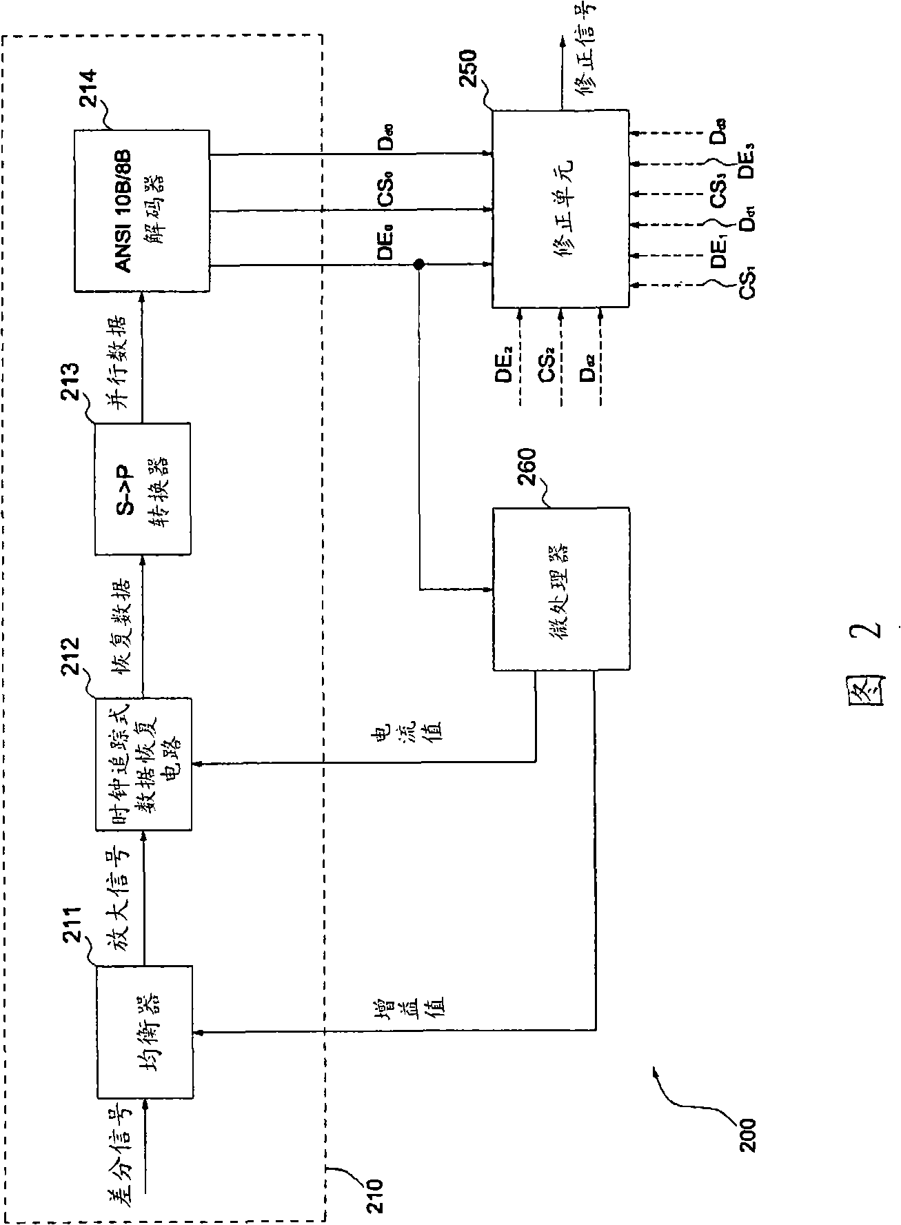
[0023] figure 2 A schematic diagram showing the framework of an embodiment of the error correction circuit of the present invention.
[0024] Referring to Figure 2, the error correction circuit 200 of the present invention is applied to the receiving end of the display port interface, and includes an equalizer 211, a clock data recovery circuit (clock data recovery, CDR) 212, and a serial to parallel Converter (serial to parallel converter) 213, an ANSI10B / 8B decoder 214, a correction unit 250, and a microprocessor (MCU) 260.
[0025] The conversion circuit 210 is set in one of the data transmission channels L of the main link 0 (When the main link has four data transmission channels, four sets of conversion circuits 210 are required), the equalizer 211 amplifies a differential signal according to a gain value g to generate an amplified signal. The clock tracking data recovery circuit 212 includes a phase-locked loop circuit (PLL) (not shown in the figure), and the clock frequen...
PUM
 Abstract
Description
Claims
Application Information
PatSnap Eureka turns technology decisions into work you can execute. Powered by our Innovation Knowledge Graph, it runs expert workflows across engineering, life sciences, materials and intellectual property. Get your review-ready output in minutes.


