Gas distribution device

A gas distribution device and gas chamber technology, applied in the direction of granular/powdered fuel gasification, combined combustion relief, etc., can solve the problems of difficult ash discharge, lower gasification efficiency, etc., and achieve the effect of prolonging residence time and strengthening horizontal mixing

Active Publication Date: 2009-09-02
ENN SCI & TECH DEV
View PDF0 Cites 7 Cited by
  • Summary
  • Abstract
  • Description
  • Claims
  • Application Information

AI Technical Summary

Problems solved by technology

When this type of distribution plate is used to gasify biomass or a mixture of coal and biomass with complex components, there is a problem of difficulty in ash removal; moreover, when adding heterogeneous materials or multi-component materials into this type of fluidized bed, It often occurs that the floating components or small particles have begun to fluidize, but the sinking components or large particles have not yet fluidized
If the fluidization gas velocity continues to increase, the sedimentation component or large-particle material will start to fluidize, and the floating component or small-particle material will elute and leave the reactor before the reaction is complete, reducing the gasification efficiency

Method used


Image

  • Gas distribution device
  • Gas distribution device
  • Gas distribution device

Examples


Embodiment 1

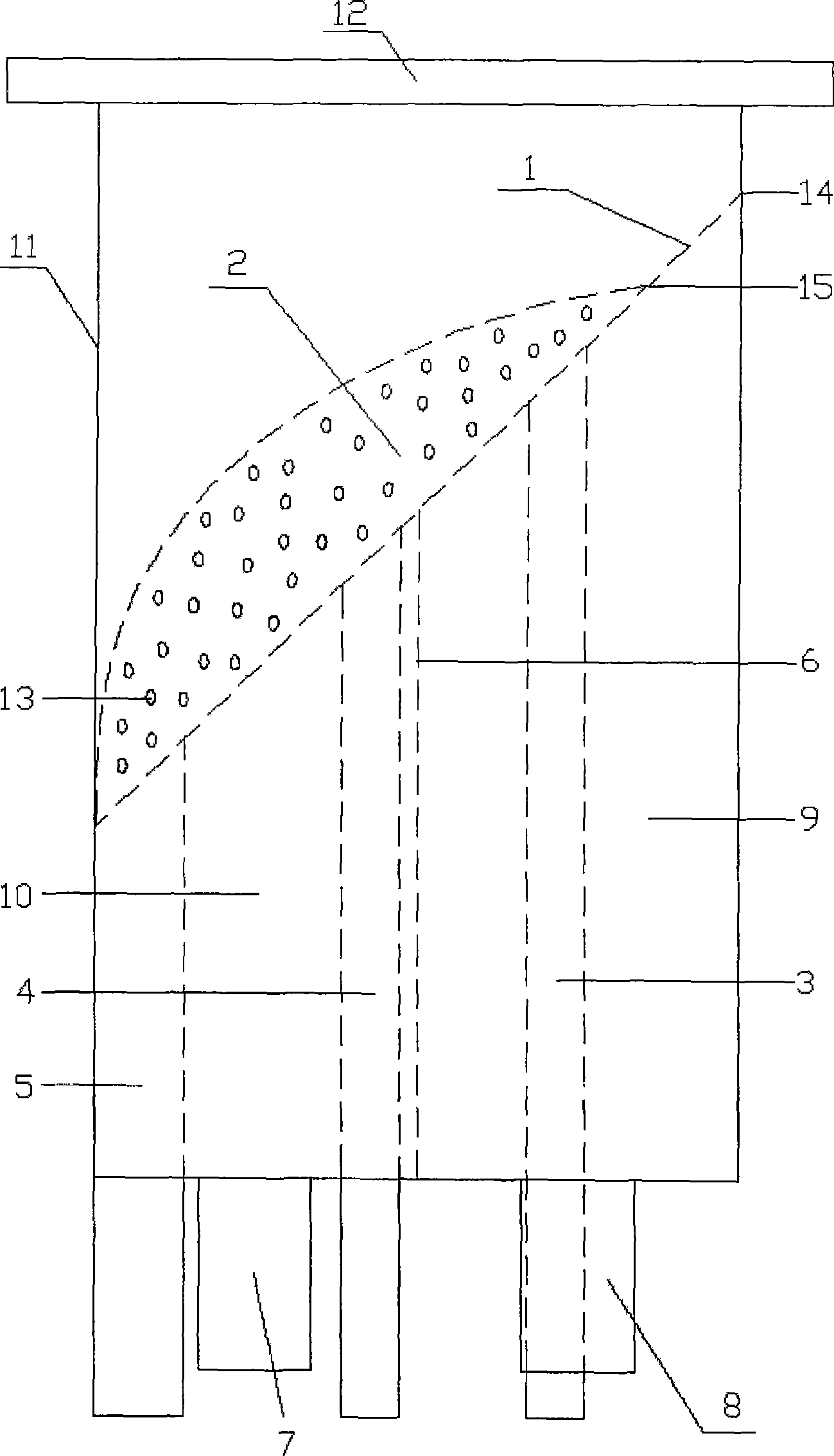
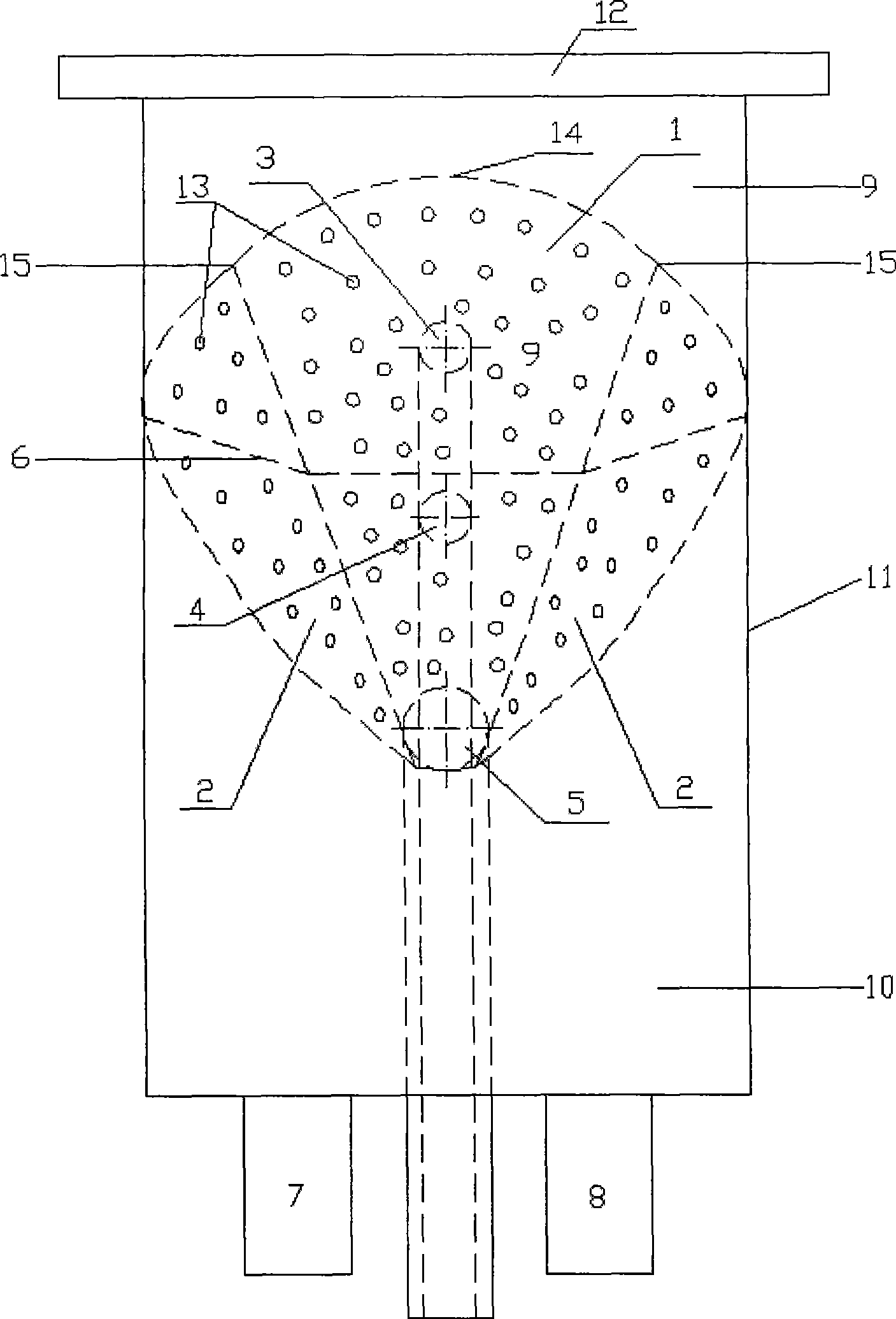
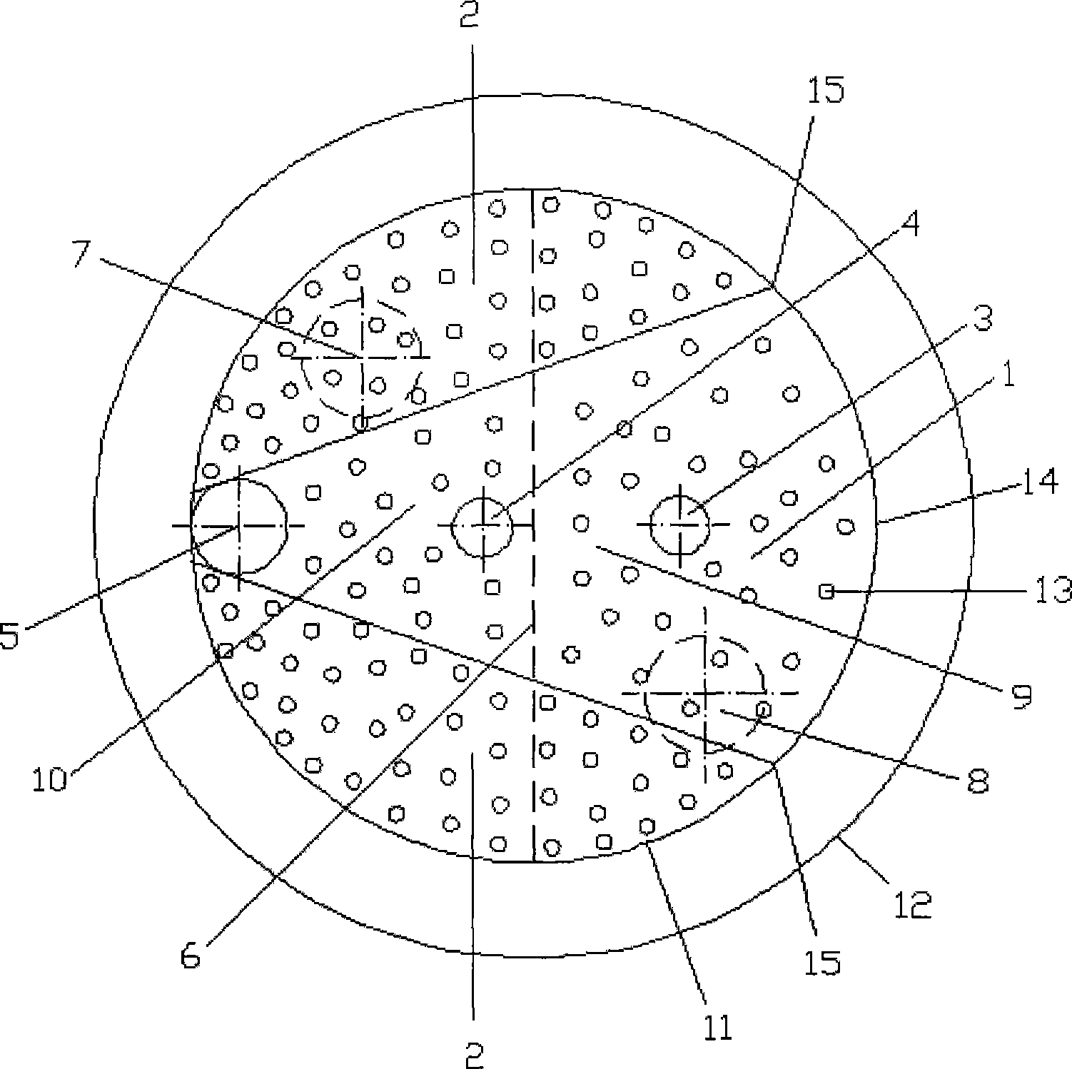
[0016] The main board 1 and the side wings 2 form a gas distribution plate. The side wings 2 are located on both sides of the main board 1, symmetrical along the center line of the main board 1, and form an angle of 20° with the plane where the main board 1 is located. The main board 1 is placed on the cylinder at an angle of 25° to the horizontal direction. The inside of 11 is connected to the wall of cylinder 11. There are vertically upward small holes 13 on the main board 1 and side wings 2. The opening rate is 0.5%, and the aperture is 0.5 mm. The ash discharge pipe 5 and the ash discharge port on the main board 1 Connected, the ash discharge port is elliptical, the connection line between the main board 1 and the side wing 2 passes through the tangent of the ellipse of the ash discharge port, the upper end point 15 of the connection line is located between the apex 14 on the main board 1 and the baffle plate 6, and the cylinder 11 has Two jet tubes 3, 4, the centers of whi...

Embodiment 2

[0019] The side wing 2 forms an angle of 30° with the plane where the main board 1 is located, and the main board 1 is placed obliquely at an angle of 40° to the horizontal direction in the cylinder 11 and connected to the wall of the cylinder 11. The main board 1 and the side wing 2 are provided with vertically upward small Hole 13, the opening ratio is 2%, and the aperture is 2 millimeters, and other is the same as embodiment 1.

Embodiment 3

[0021] The side wing 2 forms an angle of 40° with the plane where the main board 1 is located, and the main board 1 is placed obliquely at an angle of 50° to the horizontal direction in the cylinder 11 and connected to the wall of the cylinder 11. The main board 1 and the side wing 2 are provided with vertically upward small Hole 13, the opening rate is 5%, and the aperture is 3 millimeters, and other is the same as embodiment 1.


PUM

PropertyMeasurementUnit
pore sizeaaaaaaaaaa
pore sizeaaaaaaaaaa
porosityaaaaaaaaaa

Abstract

The invention relates to a gas distribution device which comprises a main board (1), lateral wings (2), a jet pipe ash-exhausting pipe (5), a baffle (6), a gas inlet pipe gas chamber, a cylinder (11) and a flange (12). A gas distribution board is formed by the main board (1) and the lateral wings (2), and the main board (1) forming an angle of 25 degrees to 60 degrees with the horizontal direction is obliquely arranged in the cylinder (11) and is connected with the wall surface of the cylinder (11); vertical upward small holes (13) are respectively arranged on the main board (1) and the lateral wings (2), and the ash-exhausting pipe (5) is communicated with an ash-exhausting hole on the main board (1); two jet pipes (3) and (4) are arranged in the cylinder (11), and the centers are respectively arranged on two equipartition points which uniformly divide the diameter of the cylinder (11) after the diameter of the ash-exhausting pipe (5) is removed; one end of the jet pipe (3) and one end of the jet pipe (4) are communicated with the main board (1), and the baffle (6) which is arranged on a midline in the cylinder (11) divides the gas chamber into two gas chambers (9) and (10) which are communicated with two gas inlet pipes (7) and (8). The invention has the advantages of easy operation, high gasification efficiency and wide material range of application.

Description

technical field [0001] The invention belongs to a gas distribution device for a fluidized bed, in particular to a gas distribution device for an internal circulating fluidized bed. Background technique [0002] With the decrease of fossil energy, the energy crisis and environmental protection have increasingly attracted the attention of countries all over the world. The development and utilization of renewable energy is an effective means to alleviate energy crisis and environmental degradation. Biomass, as an important renewable energy source, has attracted widespread attention from all over the world. Biomass mainly includes agricultural and forestry waste and domestic waste, which is characterized by complex composition, high water content, large difference in equivalent diameter, and different shape and density. The use of fluidized bed gasification of biomass for power generation or synthesis is one of the current methods of utilizing biomass energy. However, there a...

Claims


Application Information

Patent Timeline
Patent Type & Authority Applications(China)
IPC IPC(8): C10J3/56
CPCY02E20/18
Inventor 毕继诚李克忠
Owner ENN SCI & TECH DEV
Why Eureka
Try Eureka