Flow guide device and spouted bed

A technology of spouted bed and deflector, which is applied in the direction of hearth furnaces, chemical instruments and methods, furnaces, etc., to achieve the effects of reducing collision wear, simple structure, and convenient operation

Active Publication Date: 2015-01-14
西安茗博化工科技有限公司
View PDF8 Cites 0 Cited by
  • Summary
  • Abstract
  • Description
  • Claims
  • Application Information

AI Technical Summary

Problems solved by technology

But there are also disadvantages: the air flow required to maintain this sprayed-fluidized bed is larger than that required for separate spraying and separate fluidization, and a certain amount of auxiliary air supply equipment is added

Method used


Image

  • Flow guide device and spouted bed
  • Flow guide device and spouted bed
  • Flow guide device and spouted bed

Examples


Embodiment

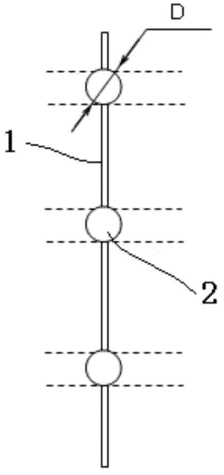
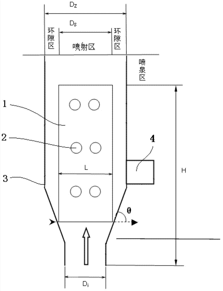
[0039] This embodiment is a specific spouted bed, such as figure 1 In the spouted bed reactor shown, a rotating and controllable deflector 1 is set on the spouted bed bed 3, and the control is realized by the speed-regulating motor 4 on the base of the spouted bed. A series of longitudinal vortex generators distributed in pairs, the diameter D of the longitudinal vortex generator sphere 2 is 4mm, and the diameter of the particles is d p is 0.46mm.

[0040] The sphere is bisected by the deflector, and the horizontal center distance of the pair of longitudinal vortex generators on the deflector is 1.5 times the diameter D of the metal ball, and the longitudinal center distance is 3 times the diameter D of the ball.

[0041] The width of the deflector is L is 20mm, D i 14.3mm, the top of the deflector is located in the area below the spouted bed fountain area to ensure that the structure of the deflector does not affect the overall spouting effect of the spouted bed.

[0042] ...


PUM


Abstract

The invention discloses a flow guide device and a spouted bed. The flow guide device comprises a flow guide plate, wherein a plurality of bulges are formed on two plate surfaces of the flow guide plate; the external surfaces of all the budges are spherical surfaces. Furthermore, the flow guide plate is of a rotary structure; the rotation direction of a flow guide plate is tangent to the flowing direction of the flow; the flow guide device is mounted on the spouted bed and is arranged below a fountain area. The flow guide device is simple in structure, easy and convenient to process and manufacture; the deficiency of lateral mixing of particles in a bed layer of a conventional spouted bed can be effectively overcome, the defect that the surfaces of part of the particles cannot be fully used can be overcome, the lateral mixing of the particles and the flow in a radial injection area and an annular space area of the spouted bed is enhanced, so that the overall mass transfer and heat transfer between the particles and the flow in the spouted bed is improved, and the overall material treatment capability of the spouted bed is increased.

Description

technical field [0001] The invention relates to a spouted bed reactor used in industries such as chemical industry, environmental protection, energy, metallurgy, etc., in particular to a flow deflector and related spouted beds. Background technique [0002] As a high-efficiency gas-solid contactor, the spouted bed has been widely used in various unit operations and unit processes, such as drying, crushing and granulation of high-viscosity particles, coarse lump particles, slurry and Combustion and gasification, coal-fired flue gas desulfurization, waste incineration flue gas desulfurization, dehydrochlorination gas, carbon dioxide removal, etc. [0003] After more than 50 years of development, spouted beds have come in many forms, among which the most widely used and typical spouted bed is column-cone spouted bed, which has an obvious three-zone flow structure: dilute phase spray zone, dense phase spouted bed Phase ring gap area and fountain area. The particles in the inje...

Claims


Application Information

Patent Timeline
IPC IPC(8): B01J8/14F26B3/08F26B21/00
CPCB01J8/14F26B3/082
Inventor 吴峰马晓迅边文娟
Owner 西安茗博化工科技有限公司
Why Eureka
Try Eureka