Method for controlling the motion of computerized pattern sewing machines

A technology of pattern sewing machine and control method, applied in electrical program control, program-controlled sewing machine, digital control and other directions, can solve the problems of low sewing speed, unstable high-speed operation, etc. beautiful effect

Inactive Publication Date: 2013-01-09
MIANYANG WEIBO ELECTRONICS
View PDF3 Cites 0 Cited by
  • Summary
  • Abstract
  • Description
  • Claims
  • Application Information

AI Technical Summary

Problems solved by technology

[0005] In order to solve the problem of low sewing speed and unstable high-speed operation of computerized pattern sewing machines

Method used


Image

  • Method for controlling the motion of computerized pattern sewing machines
  • Method for controlling the motion of computerized pattern sewing machines
  • Method for controlling the motion of computerized pattern sewing machines

Examples


Embodiment Construction

[0020] The motion control method of the computerized pattern sewing machine of the present invention will be further described in detail below in conjunction with the accompanying drawings.

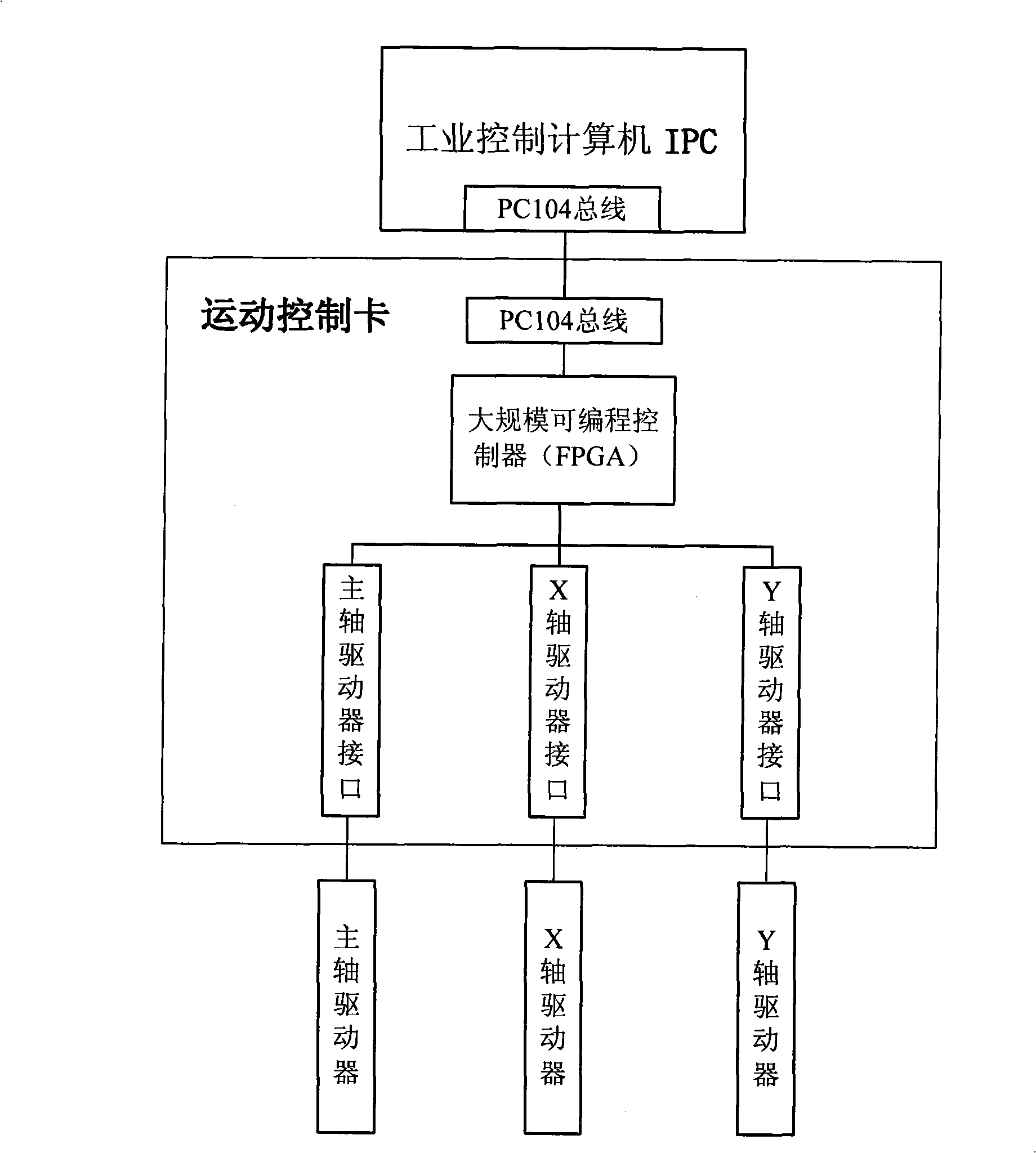
[0021] From figure 1 It can be seen that the present invention is realized on the platform of a computerized pattern sewing machine control system. The control system includes a computer control unit, a servo drive unit, a man-machine interface unit, a system power supply unit, and system software. The computer control unit is the core part of the present invention, and is also the basis for the realization of the method provided by the present invention. The computer pattern sewing machine is composed of an industrial control computer (IPC), a motion control card and an output interface card. The computer pattern sewing machine is responsible for the operation of the system software, realizing screen display, key input, file management, 3 axes (spindle, X axis, Y axis) Motion control, ...


PUM


Abstract

The invention provides a method for controlling the motion of computerized pattern sewing machines. The method is that a controlling system controls the feeding movement of an X-axis and a Y-axis by dThe invention provides a method for controlling the motion of computerized pattern sewing machines. The method is that a controlling system controls the feeding movement of an X-axis and a Y-axis by detecting the angle of a spindle servo motor when the spindle servo motor is running uniformly. An industrial controlling computer and a Field Programmable Gate Array (FPGA) process and control the movetecting the angle of a spindle servo motor when the spindle servo motor is running uniformly. An industrial controlling computer and a Field Programmable Gate Array (FPGA) process and control the movement respectively, i.e., the data operated by CPU is stored in sequence in an array provided by the FPGA and the FPGA fetches and controls the data in the array in sequence. The computer and the FPGAement respectively, i.e., the data operated by CPU is stored in sequence in an array provided by the FPGA and the FPGA fetches and controls the data in the array in sequence. The computer and the FPGArun at the same time thus greatly saving controlling time and raising the sewing speed. The computerized pattern sewing machines adopting the method has the advantages of high speed, smooth operation run at the same time thus greatly saving controlling time and raising the sewing speed. The computerized pattern sewing machines adopting the method has the advantages of high speed, smooth operation, low noise and beautiful and even stitch. The method is applicable to the motion control of the current computerized pattern sewing machines or other similar industrial sewing machines., low noise and beautiful and even stitch. The method is applicable to the motion control of the current computerized pattern sewing machines or other similar industrial sewing machines.

Description

technical field [0001] The invention relates to a motion control method in the field of numerical control, in particular to a motion control method for a computerized pattern sewing machine. Background technique [0002] Pattern sewing machine is an indispensable and important sewing equipment in the production process of bags, shoes and hats. The motion control method adopted by the computerized pattern sewing machine directly affects the performance index of the computerized pattern sewing machine. [0003] The Chinese patent document with the publication number CN1794561A discloses an invention patent application technology entitled "Electronic Pattern Sewing Machine Motor Motion Control Method", which discloses an electronic pattern sewing machine motor motion control method. Although this method realizes the continuous operation of the main shaft motor, the speed of the main shaft motor must be changed when each stitch is sewn. Such a control method is difficult to ach...

Claims


Application Information

Patent Timeline
Patent Type & Authority Patents(China)
IPC IPC(8): D05B21/00D05B19/16G05B19/18
Inventor 赵逸鸣杨奕昕王泓仁李杰袁敏娟赵毅忠刘玲
Owner MIANYANG WEIBO ELECTRONICS
Why Eureka
Try Eureka