
High-frequency distribution transformer

A distribution transformer and high-frequency technology, which is applied in the field of power electronic power conversion, can solve the problems of three-phase imbalance, flammability, and large volume, and achieve the effects of eliminating grid-side current harmonics and reducing size and weight

Inactive Publication Date: 2009-09-02
ZHEJIANG UNIV
View PDF0 Cites 16 Cited by
  • Summary
  • Abstract
  • Description
  • Claims
  • Application Information

AI Technical Summary

Problems solved by technology

This type of distribution transformer has four disadvantages: (1) The power factor of the low-voltage side (that is, the load side) directly affects the high-voltage side, and the load with too low power factor must require power factor compensation; (2) The harmonics on the load side are all If it flows into the power grid, it will cause many harms, and harmonic compensation is required; (3) Factors such as three-phase unbalance, overload, and short-circuit faults on the load side will directly affect the power quality and power supply reliability of the power grid
(4) Usually this type of power frequency distribution transformer is mostly oil-immersed, which has inherent disadvantages such as large volume, many materials, and flammability.

Method used


Image

  • High-frequency distribution transformer
  • High-frequency distribution transformer
  • High-frequency distribution transformer

Examples


Embodiment Construction

[0016] The present invention will be further described below in conjunction with the accompanying drawings and specific embodiments.

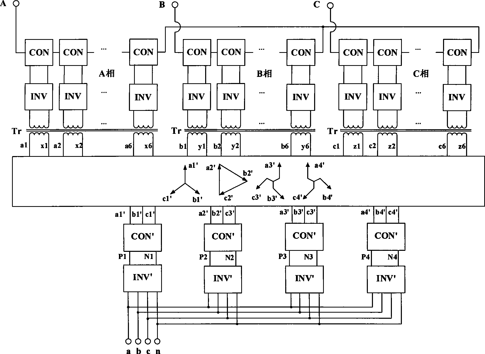
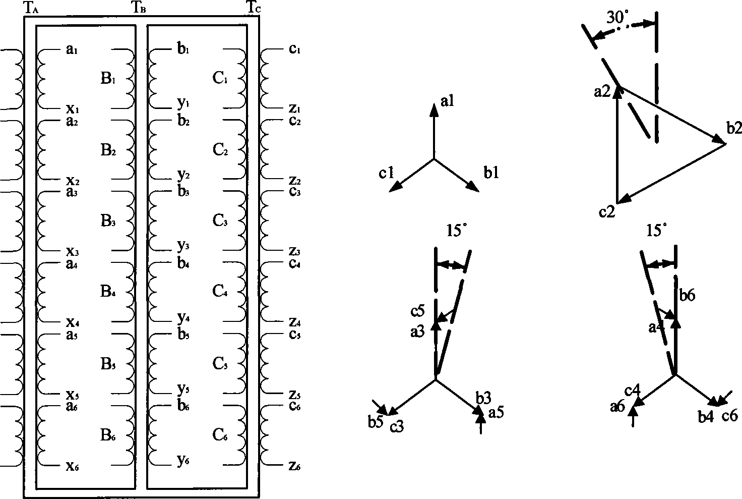
[0017] refer to figure 1 , the high-frequency distribution transformer includes a three-phase voltage high-frequency modulation circuit, a high-frequency phase-shifting transformer Tr, a multi-pulse rectifier circuit CON', and an inverter output module INV'; in the illustration, a three-phase voltage high-frequency modulation circuit Each phase bridge arm in includes 6 series-connected single-phase rectifier modules CON and 6 series-connected inverter groups INV, that is, the case where n=6, m=1; each phase bridge arm has 6 series-connected single-phase rectifier modules CON The first end of the three-phase grid is connected to the incoming line of the high-voltage side, and the end is connected to the midpoint of the three-phase grid. The output terminals of the six single-phase rectifier modules CON are respectively connected to the input ter...


PUM


Abstract

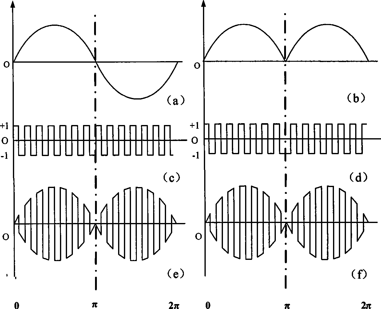
The invention discloses a high-frequency distribution transformer, which comprises a three-phase voltage high-frequency modulation circuit, high-frequency phase-shifting transformer, a multi-pulse rectifying circuit, and an inverter output module, wherein each phase of bridge arm of the three-phase voltage high-frequency modulation circuit comprises n serially-connected single-phase rectifying modules and inverter modules of which the number is m times of that of the single-phase rectifying modules. Output voltage of the high-frequency distribution transformer can be adjusted by adjusting the duty cycle of the inverter modules in three-phase voltage high-frequency modulation circuit; the operation of the high-frequency phase-shifting transformer in a high-frequency modulation mode can effectively reduce the volume and weight of the whole distribution transformer; and the distribution transformer can solve the flow equalization problem of the multi-pulse rectifying circuit, allows a power factor on the line side to be close to 1 and substantially eliminates the current harmonics on the line side. The high-frequency distribution transformer is applicable to the prior power frequency power distribution system and multiphase power distribution system as well as high-frequency power distribution system such as 400Hz ship power distribution system.

Description

technical field [0001] The invention relates to a high-frequency distribution transformer, which belongs to the technical field of power electronic power conversion. Background technique [0002] At present, the high-voltage side of the distribution transformer is mostly three-phase 10kV input, and the low-voltage side is 380V / 220V low-voltage three-phase four-wire system output. This type of distribution transformer has four disadvantages: (1) The power factor of the low-voltage side (that is, the load side) directly affects the high-voltage side, and the load with too low power factor must require power factor compensation; (2) The harmonics on the load side are all If it flows into the power grid, it will cause many harms, and harmonic compensation is required; (3) Factors such as three-phase imbalance, overload, and short-circuit faults on the load side will directly affect the power quality and reliability of the power grid. (4) Usually this type of power frequency dis...

Claims


Application Information

Patent Timeline
Patent Type & Authority Applications(China)
IPC IPC(8): H02M5/42H02J3/38H01F30/12H01F27/28
CPCY02E40/10
Inventor 赵荣祥吕征宇胡海兵汪槱生
Owner ZHEJIANG UNIV
Learn More