Thermal cycling system

A thermal cycler and heat transfer coefficient technology, applied in the field of thermal cycle systems, can solve problems such as insufficient temperature change speed, expensive optical detection elements, and inability to achieve optimal performance.

Inactive Publication Date: 2009-09-02
CALIFORNIA INST OF TECH
View PDF14 Cites 83 Cited by
  • Summary
  • Abstract
  • Description
  • Claims
  • Application Information

AI Technical Summary

Problems solved by technology

Cycling at the desired temperature level is less efficient due to the large thermal mass of the thermal cycler and the poor thermal conductivity of the sample vessel
Conventional thermal cyclers are often not ramped fast enough, inevitably leading to undesired non-specific amplifi

Method used


Image

  • Thermal cycling system
  • Thermal cycling system
  • Thermal cycling system

Examples


Embodiment 1

[0214] Stainless Steel PCR Sample Tank

[0215] Stainless steel PCR sample wells have proven to be suitable vessels in which to perform the polymerase chain reaction. The vessel used for the initial testing was made of stainless steel tubing with a final outside diameter of 0.061 inches. The two inch long sample wells are closed at one end with a pressure fit stainless steel plug.

[0216] 20 μL of the same preparation for real-time polymerase chain reaction (using SYBR green intercalating dye as an indicator) was simultaneously placed in a commercially available glass PCR capillary tube and the metal sample holder described above. The reagents were then isolated from the outside air in each container by using 20 μL of mineral oil as an upper liquid layer. These containers were temperature cycled together for 40 cycles in a commercial real-time PCR machine, after which the contents of the metal sample wells were transferred to commercial glass PCR capillaries. Melting curve...

Embodiment 2

[0218] Real-time PCR

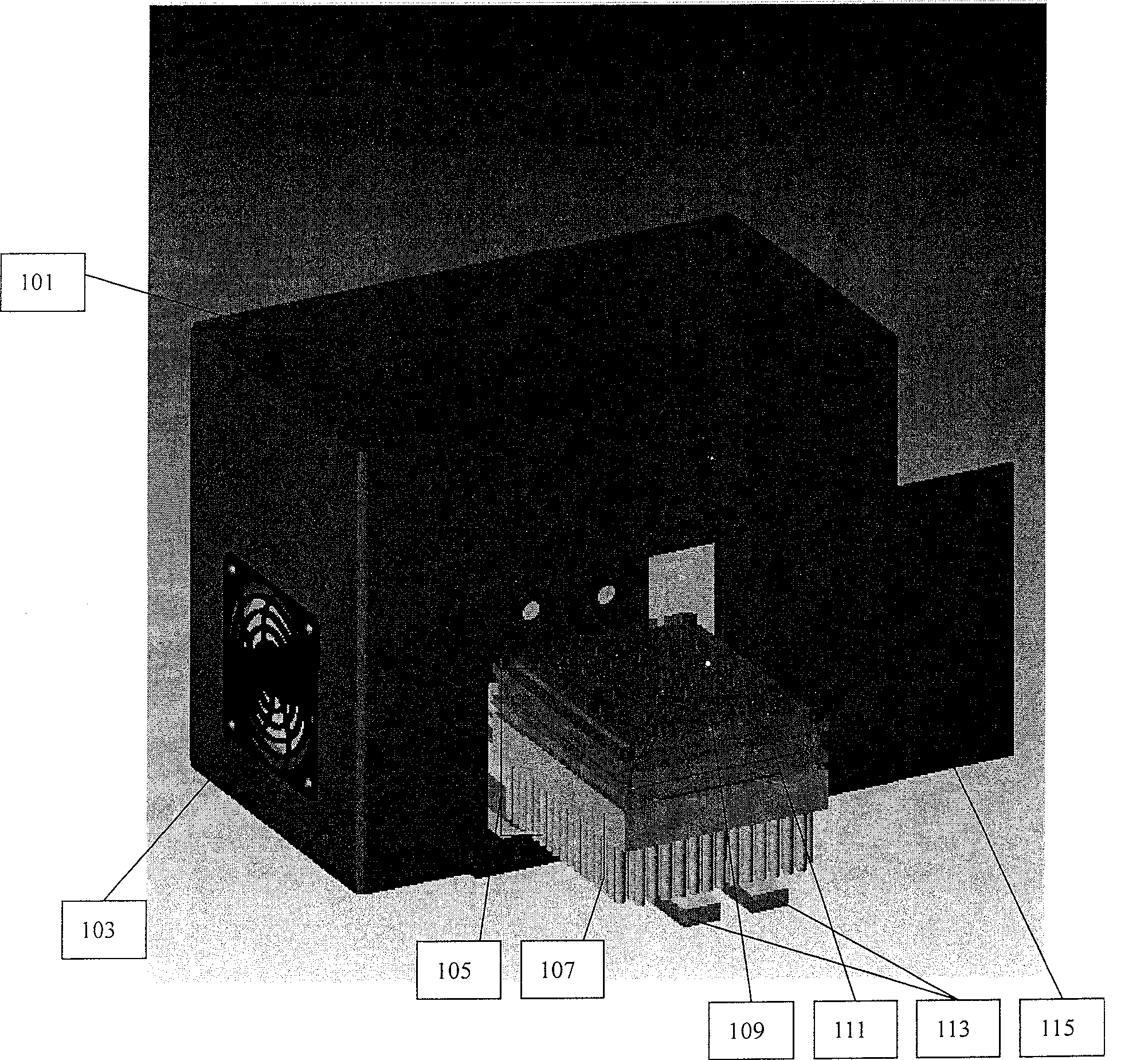
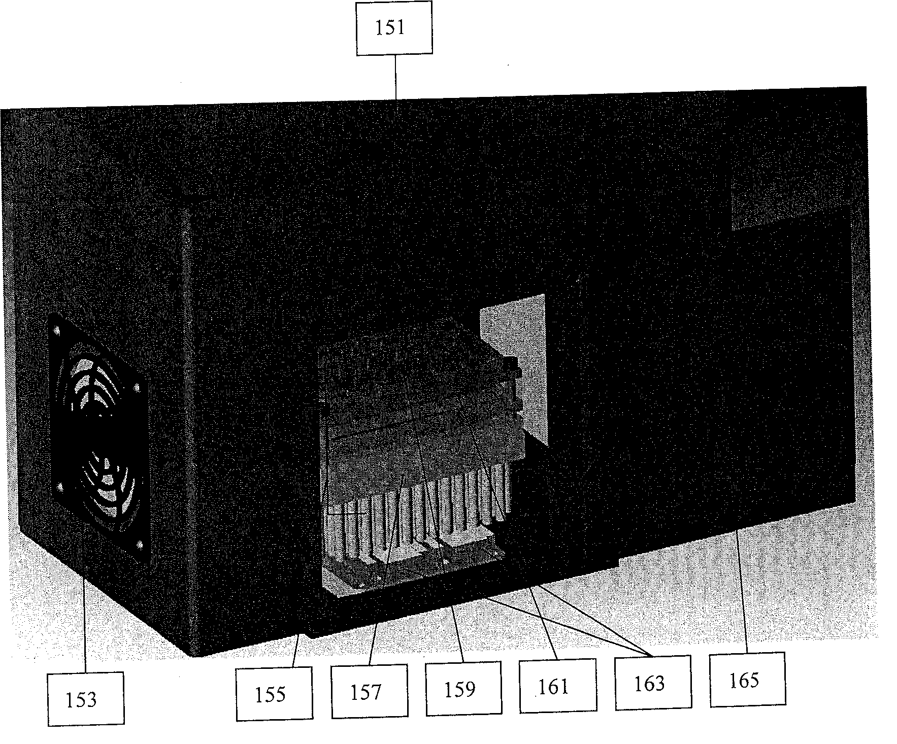
[0219] Liquid metal or thermal fluid heating blocks are ideal for real-time PCR reactions due to their fast ramp rates, thermal uniformity, and reflectivity.

[0220] Prepare the sample wells by adding the PCR reaction components to the wells and sealing the containers to prevent spillage or cross-contamination. Reaction components include buffer, target nucleic acid, appropriate primers and probes, nucleotides, polymerase, and optional additional components. In one embodiment, four fluorescent probes are included, each for detecting a different target sequence, and a particular reaction vessel may include any one or more of the fluorescent probes. Each probe advantageously responds to light having a different incident wavelength and emits light at a different wavelength.

[0221] A detection module is installed on the heating block. The detection module includes four detection channels. Each channel is optimized for one of the different fluorescent ...


PUM


Abstract

This invention provides a system for performing PCR, and real time PCR in particular, with great speed and specificity. The system employs a heat block containing a liquid composition to rapidly transfer heat to and from reaction vessels. The system makes use of the reflective properties of the liquid metal to reflect signal from the PCR into the vessel and out the top. In this way, the signal can be measured by an optical assembly in real time without removing the vessels from the heat block.

Description

[0001] cross reference [0002] This application claims 60 / 801178 filed 5 / 17 / 06, 60 / 832492 filed 7 / 22 / 06, 60 / 873084 filed 12 / 06 / 06 and 60 / 873084 filed 12 / 06 / 06 Priority to US Provisional Application No. 60 / 873,172, which are incorporated herein by reference. Background technique [0003] Invented by Kary Mullis in 1983, PCR has been hailed as one of the most important scientific developments of the 20th century. PCR technology has revolutionized molecular biology by greatly expanding the ability to identify and reproduce genetic material such as DNA. Today, PCR is routinely used in medical as well as biological research laboratories to perform a variety of tasks such as the detection of genetic diseases, the identification of genetic fingerprints, the diagnosis of infectious diseases, the cloning of genes, paternity testing and DNA calculate. This method has been automated through the use of thermostable DNA polymerases and a machine commonly referred to as a "thermocycler...

Claims


Application Information

Patent Timeline
IPC IPC(8): C12Q1/68C12Q1/10
Inventor G·马尔特佐斯M·约翰斯顿D·古德温A·谢勒C·I·沃克
Owner CALIFORNIA INST OF TECH
Why Eureka
Try Eureka