

Induction coil for cordless energy charging and data transfer
An induction coil and wireless charging technology, which is applied in battery data exchange, inductors, fixed inductors, etc., can solve the problems of reduced power transmission efficiency, complicated series connection, and shortened lifespan.
- Summary
- Abstract
- Description
- Claims
- Application Information
AI Technical Summary
Problems solved by technology
Method used
Image

Examples
example 1
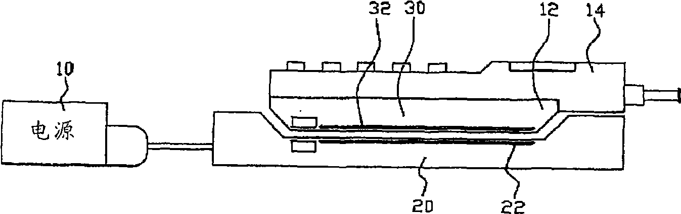
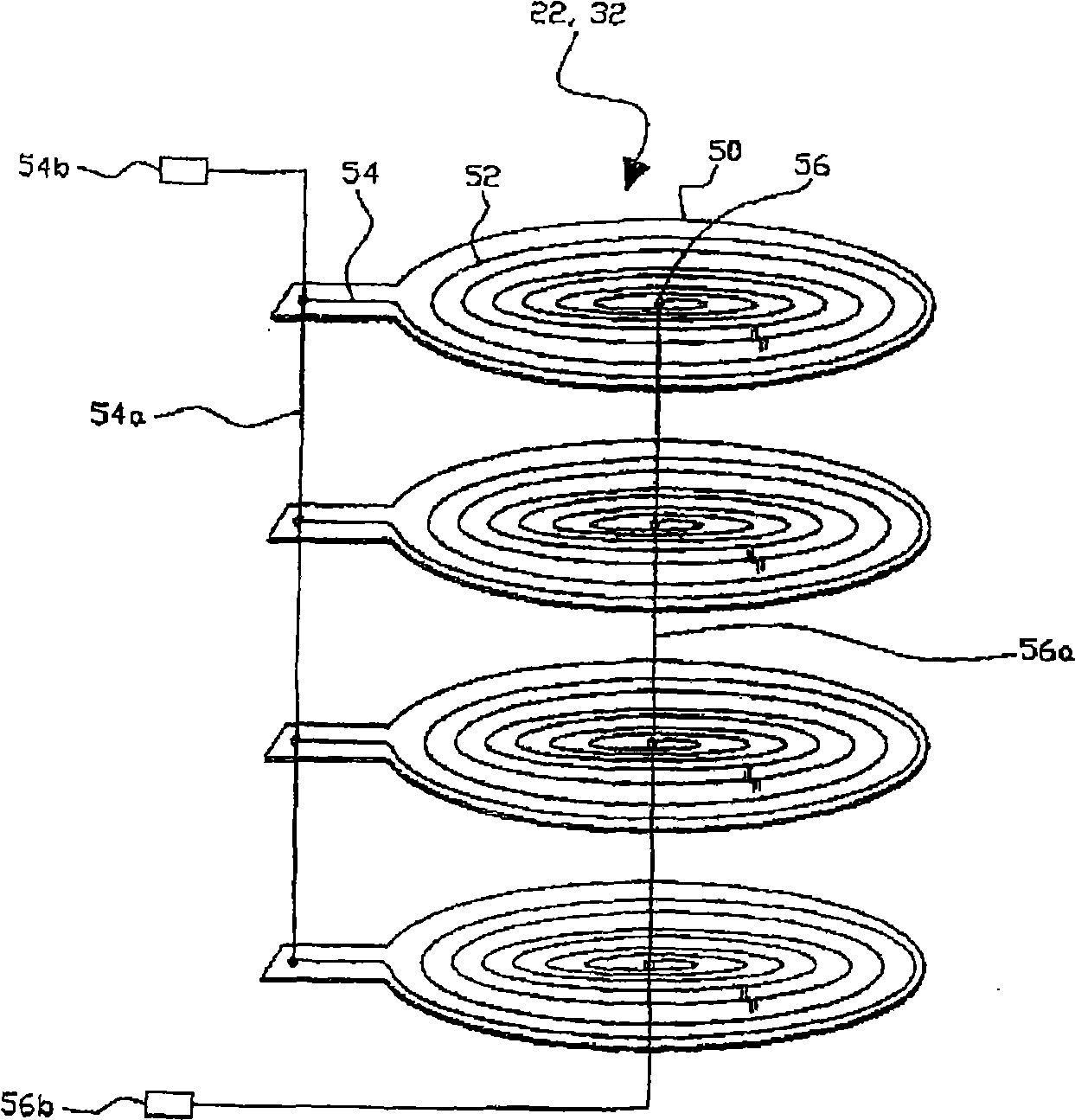
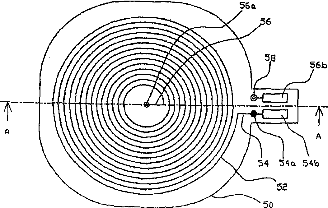
[0028] A spiral circuit pattern with a winding number of 18 turns, an outer diameter of 42 mm, a thickness (thickness of the circuit) of 0.65 mm, and a distance between patterns of 0.2 mm is formed on the upper part of a polyimide film with a thickness of 10 μm by using copper , and then stacked 8 layers, is used as the transfer main winding of the pad type current transfer part. A spiral circuit pattern in which the number of turns of the winding is 18, the outer diameter is 30 mm, the thickness (thickness of the circuit) is 0.54 mm, and the distance between the patterns is 0.2 mm is formed on a polyimide film with a thickness of 10 μm by using copper On the upper part, 4 layers are then stacked to be used as the receiving secondary winding of the pad type current receiving part. The current transmitting part is in contact with the current receiving part, and a current of 0.151A and 4.62V is applied to the transmitting main winding, and then the current and voltage generated ...
example 2
[0030] The same transfer main winding in Example 1 was used as the transfer main winding of the pad type current transfer section. A spiral circuit pattern in which the number of turns of the winding is 18, the outer diameter is 35 mm, the thickness (thickness of the circuit) is 0.67 mm, and the distance between the patterns is 0.2 mm is formed on a polyimide film with a thickness of 10 μm by using copper On the upper part, 5 layers are then stacked to be used as the receiving secondary winding of the pad type current receiving part. The current transmitting part is in contact with the current receiving part, and a current of 0.151A and 4.62V are applied to the transmitting main winding, and then the current and voltage generated in the receiving secondary winding are measured, and accordingly, a current of 0.115A and 3.85V are detected, And the power transfer efficiency is 63%.
example 3
[0032] The same transfer main winding in Example 1 was used as the transfer main winding of the pad type current transfer section. The number of turns of the winding is 16, the outer diameter is 34 mm, the thickness (thickness of the circuit) is 0.75 mm, and the distance between the patterns is 0.2 mm. The rectangular circuit pattern is formed by using copper on a polyimide film with a thickness of 10 μm. On the upper part, 6 layers are then stacked to be used as the receiving secondary winding of the pad type current receiving part. The current transmitting part is in contact with the current receiving part, and a current of 0.151A and 4.62V are applied to the transmitting main winding, and then the current and voltage generated in the receiving secondary winding are measured, and accordingly, a current of 0.119A and 3.88V are detected, And the power transfer efficiency is 65%.
PUM
| Property | Measurement | Unit |
|---|---|---|
| Thickness | aaaaa | aaaaa |
| Outer diameter | aaaaa | aaaaa |
| Outer diameter | aaaaa | aaaaa |
Abstract
Description
Claims
Application Information