Casting device, and solution casting method and apparatus
A technology of casting and casting molds, applied in application, coating, household appliances, etc., can solve the problems of poor work efficiency, reduced production efficiency, and limited efficient production, so as to prevent uneven thickness and pressure fluctuating effect
- Summary
- Abstract
- Description
- Claims
- Application Information
AI Technical Summary
Problems solved by technology
Method used
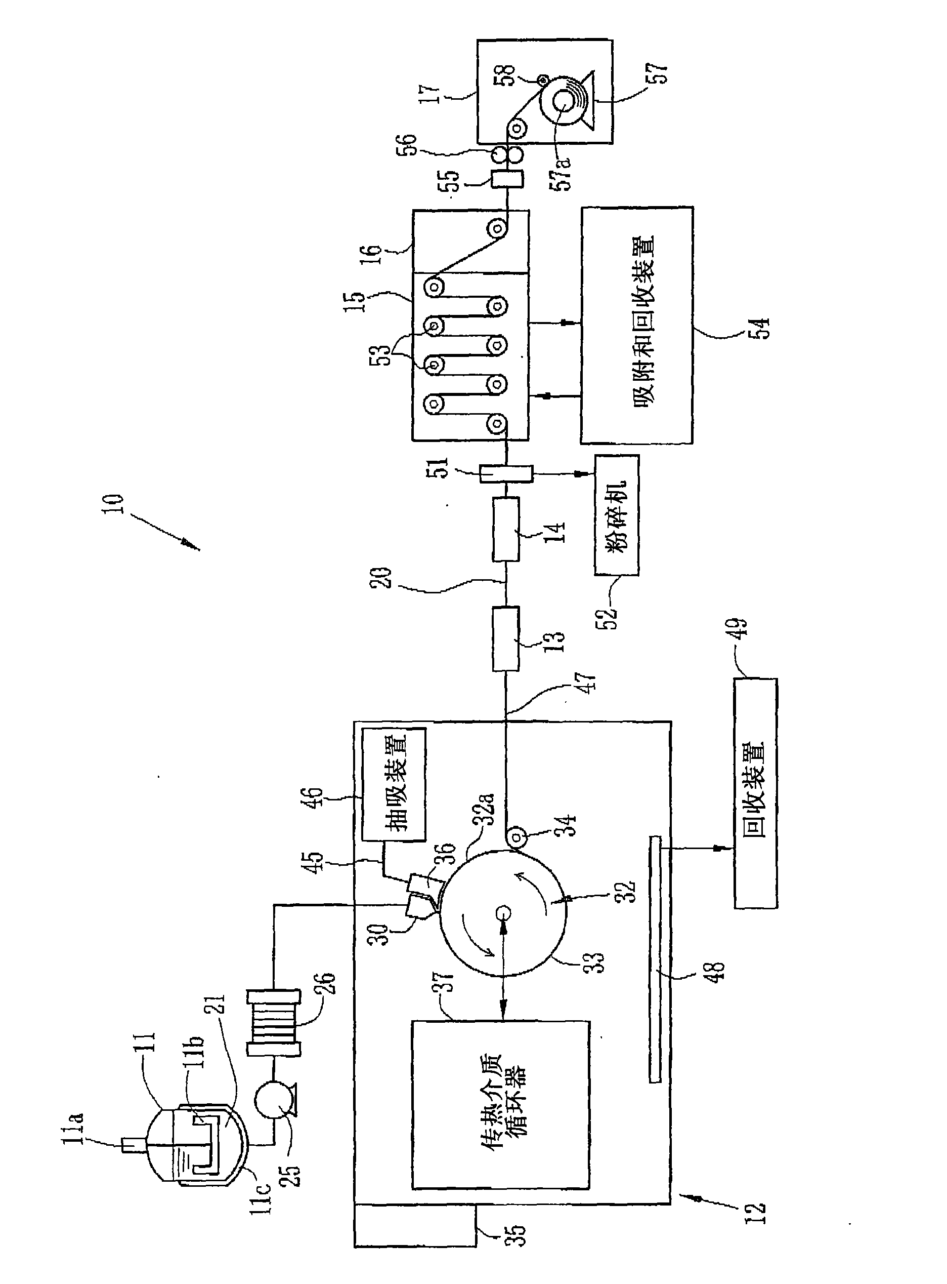
Image

Examples
Embodiment 1
[0071] (experiment 1)
[0072] In Experiment 1, using Figure 11 The decompression chamber 100 shown in. The decompression chamber 100 is composed of a housing 101 and a transverse labyrinth baffle 77 . The case 101 is a box, and is set on the carrier 102 . The casing 101 is composed of a top plate, a pair of side plates, and a front plate. Each of the bottom and the rear of the housing 101 has an opening, and the chamber 101a is exposed outside through each opening. A lateral labyrinth baffle 77 is provided on the rear side of the housing 101 having an opening to close the opening. A pair of side panels and a front panel are arranged to face the carrier 102 . Therefore, the chamber 101a is substantially airtight. The lateral labyrinth baffle 77 is composed of four sealing members 85 arranged in close contact with each other in the X-up direction. Thus, forming 3 Figure 5 The labyrinth groove 87 shown in. Note that in order to prevent the complexity of the drawings, in...
Embodiment approach 2
[0081] (Experiment 1)
[0082] The duct suction air flow rate V measured at a predetermined decompression degree P was examined under the same conditions as those of Experiment 1 of Example 1, except that the position of the lateral labyrinth baffle 77 was adjusted so that the sealing gap G was Half of the sealing gap G in Experiment 1 of Example 1.
[0083] (experiment 2)
[0084] The duct suction air flow rate V measured at a predetermined degree of decompression P was examined under the same conditions as those of Experiment 2 of Example 1, except that the position of the lateral labyrinth baffle 91 was adjusted so that the sealing gap G was Half of the sealing gap G in Experiment 2 of Example 1.
[0085] (Experiment 3)
[0086] The duct suction air flow rate V measured at a predetermined degree of decompression P was examined under the same conditions as those of Experiment 2 of Example 1, except that the position of the sealing member was adjusted so that the seal gap ...
PUM
| Property | Measurement | Unit |
|---|---|---|
| width | aaaaa | aaaaa |
Abstract
Description
Claims
Application Information