Pitch-play-removing roller gear-elliptic gear transmission system separately inserting mechanism

A technology for elliptical gears and backlash elimination, which is applied to transmission devices, belts/chains/gears, transplanting machinery, etc., and can solve the problem of affecting the uniformity of seedling harvesting and transplanting quality, and unfavorable elimination of backlash devices, processing and assembly errors and other problems, to achieve the effect of good uprightness of seedlings, large gear modulus, and elimination of backlash

Inactive Publication Date: 2009-09-16
ZHEJIANG SCI-TECH UNIV
View PDF0 Cites 7 Cited by
  • Summary
  • Abstract
  • Description
  • Claims
  • Application Information

AI Technical Summary

Problems solved by technology

[0003] There is no tooth backlash in the cylindrical tooth-elliptical gear transmission mechanism from a theoretical point of view, but in practical applications, due to machining and assembly errors, as well as wear in use, the tooth backlash will occur when the cylindrical tooth gear meshes and the elliptical gear meshes, causing The planting arm vibrates during work, which affects the uniformity of the amount of seedlings taken and the quality of transplanted seedlings
It is not conducive to install a device for eliminating backlash in the existing linear arrangement of cylindrical teeth-elliptical gear transmission system.

Method used


Image

  • Pitch-play-removing roller gear-elliptic gear transmission system separately inserting mechanism
  • Pitch-play-removing roller gear-elliptic gear transmission system separately inserting mechanism
  • Pitch-play-removing roller gear-elliptic gear transmission system separately inserting mechanism

Examples


Embodiment Construction

[0027] The present invention will be further described below in conjunction with drawings and embodiments.

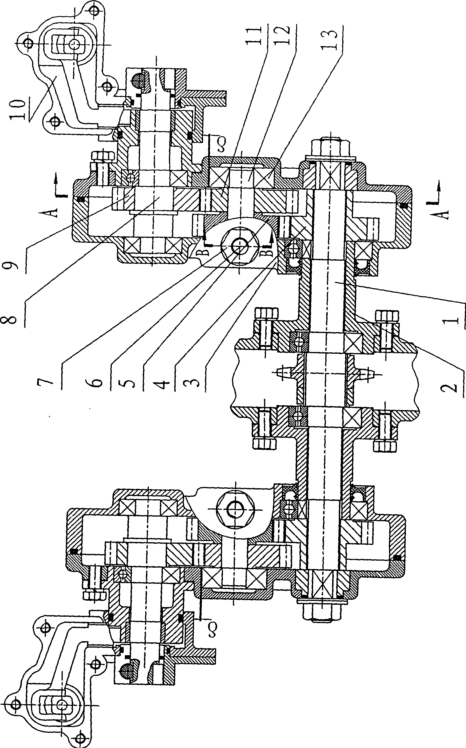
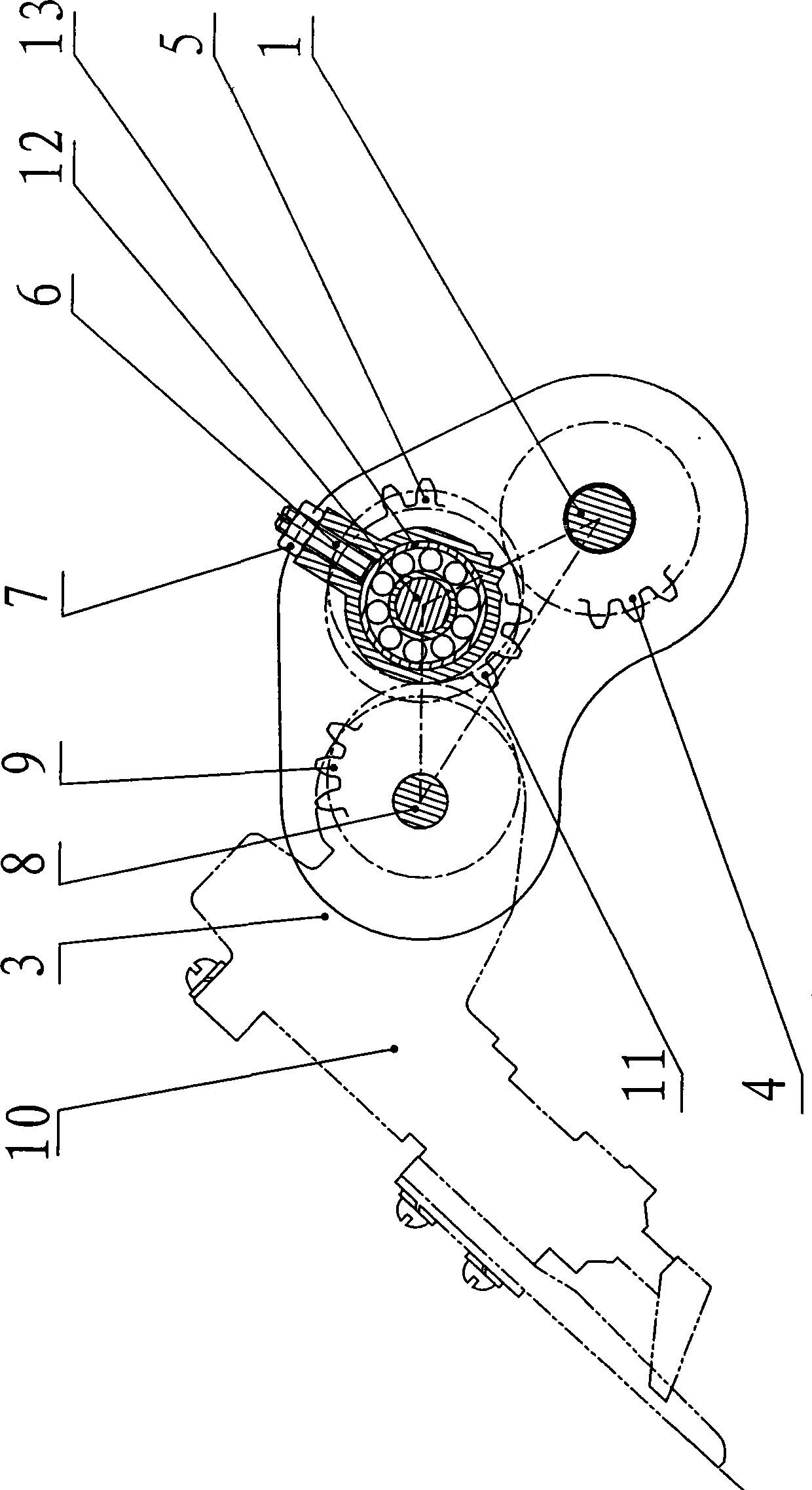
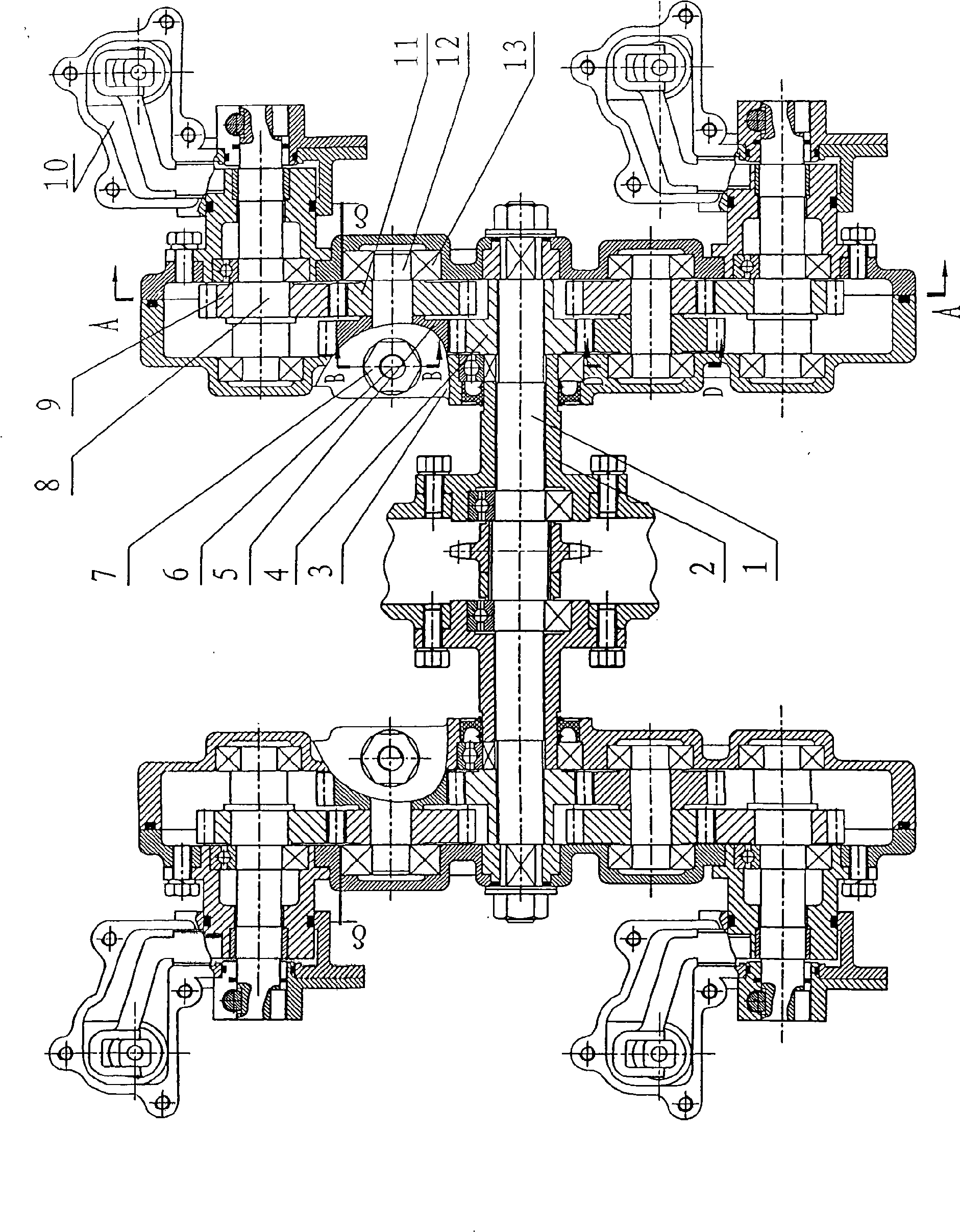
[0028] like figure 1 , figure 2 Shown, the present invention comprises the same left and right transmission box body of structure being installed respectively at central axis 1 two ends, is contained in the planting arm on left and right transmission box body one side. The structure inside the right transmission case 3 is as follows: the right central cylindrical gear 4, which is vacantly sleeved on the right end of the central shaft 1, is fixedly connected with the frame through the tooth-embedded right flange 2, and is installed in sequence on one side of the right central cylindrical gear 4. The right intermediate cylindrical gear 5 and the right intermediate elliptical gear 11 fixed on the right intermediate shaft 12 and the right planetary elliptical gear 9 fixed on the right planetary shaft 8, one end of the right planetary shaft 8 protruding from the right tran...


PUM


Abstract

The invention discloses a pitch-play-removing roller gear-elliptic gear transmission system separately inserting mechanism. A central roller gear sleeved at both ends of the central shaft is fixedly connected with a frame by a flange, a middle shaft and a planet shaft are arranged at one side of the central roller gear in sequence or two middle shafts and two planet shafts are arranged at both sides of the central roller gear symmetrically in sequence, a middle roller gear and a middle elliptic gear are respectively engaged with the central roller gear and a planet elliptic gear. Viewed from the side, the axle centers of the central shaft, the middle shaft and the planet shaft are in triangle or the axle centers of the central shaft, two middle shafts and two planet shafts are arranged in two equilateral triangles vertically-opposite on the central shaft. Both ends of the central shaft are movably supported in the hole of the transmission case body by the bearing, a gap delta is arranged between the bearing and the hole, an adjusting screw is radially arranged on the transmission case body along the middle shaft, or a spring leaf close to the outer ring of the bearing is arranged at one side in the hole of the bearing, for removing the gear side gap between the central gear and the middle gear as well as the planet gear. The invention has the advantages that the gear gap is removed, the transmission is stable and the transplanting open is little, the separately inserting mechanism can be used for a walking and seating transplanter.

Description

technical field [0001] The invention relates to agricultural machinery, in particular to a column-tooth-ellipse-gear drive train splitting mechanism for a rice transplanter that can eliminate backlash. Background technique [0002] In the existing published literature on the transplanting mechanism of the rice transplanter, the arrangement of the central gear, the intermediate gear and the planetary gear in the spur gear-elliptical gear transmission system is mainly linear. The advantage of linear arrangement is that the initial installation angle is easy to determine, and the design and calculation are more convenient. However, its volume and shape are relatively large, and it is only suitable for high-speed rice transplanters. [0003] There is no tooth backlash in the cylindrical tooth-elliptical gear transmission mechanism from a theoretical point of view, but in practical applications, due to machining and assembly errors, as well as wear in use, the tooth backlash wil...

Claims


Application Information

Patent Timeline
Patent Type & Authority Applications(China)
IPC IPC(8): A01C11/02F16H37/00
Inventor 武传宇赵匀
Owner ZHEJIANG SCI-TECH UNIV
Why Eureka
Try Eureka