Triangular weaving mechanism

A technology of triangle and circle transfer triangle, which is applied in the direction of weft knitting, knitting, textiles and papermaking, etc. It can solve the problems of lengthening the running stroke of the machine head, increasing manufacturing costs, and reducing weaving efficiency, so as to reduce consumables and improve weaving efficiency , the effect of shortening the length

Inactive Publication Date: 2009-09-16
冯加林 +1
View PDF1 Cites 4 Cited by
  • Summary
  • Abstract
  • Description
  • Claims
  • Application Information

AI Technical Summary

Problems solved by technology

[0004] If the triangular knitting mechanism of the above structure is enlarged in a certain proportion to make a corresponding thick gauge triangular knitting mechanism, the bottom plate in the knitting mechanism will not only widen in width, but also lengthen correspondingly, which will inevitably lengthen the running stroke of the machine head. This will reduce the weaving efficiency
At the same time, the extension of the length of the knitting machine will increase the consumables and increase the manufacturing cost

Method used


Image

  • Triangular weaving mechanism
  • Triangular weaving mechanism
  • Triangular weaving mechanism

Examples


Embodiment Construction

[0027] The present invention and its advantages will be further described below in conjunction with the accompanying drawings and embodiments.

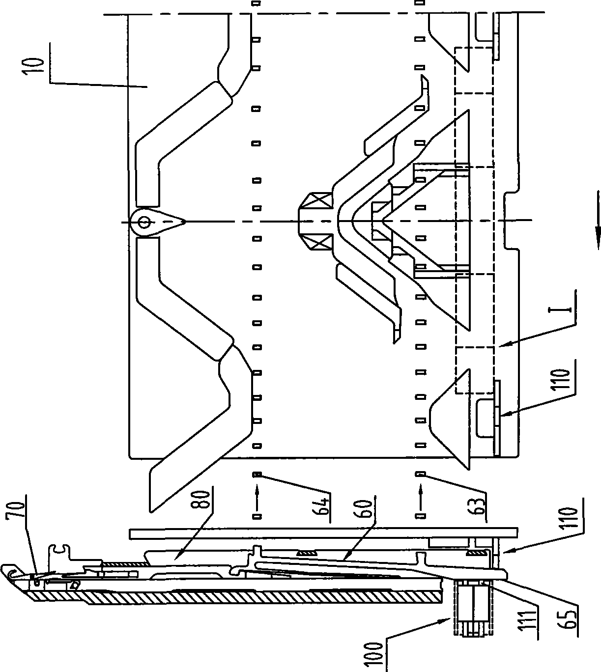
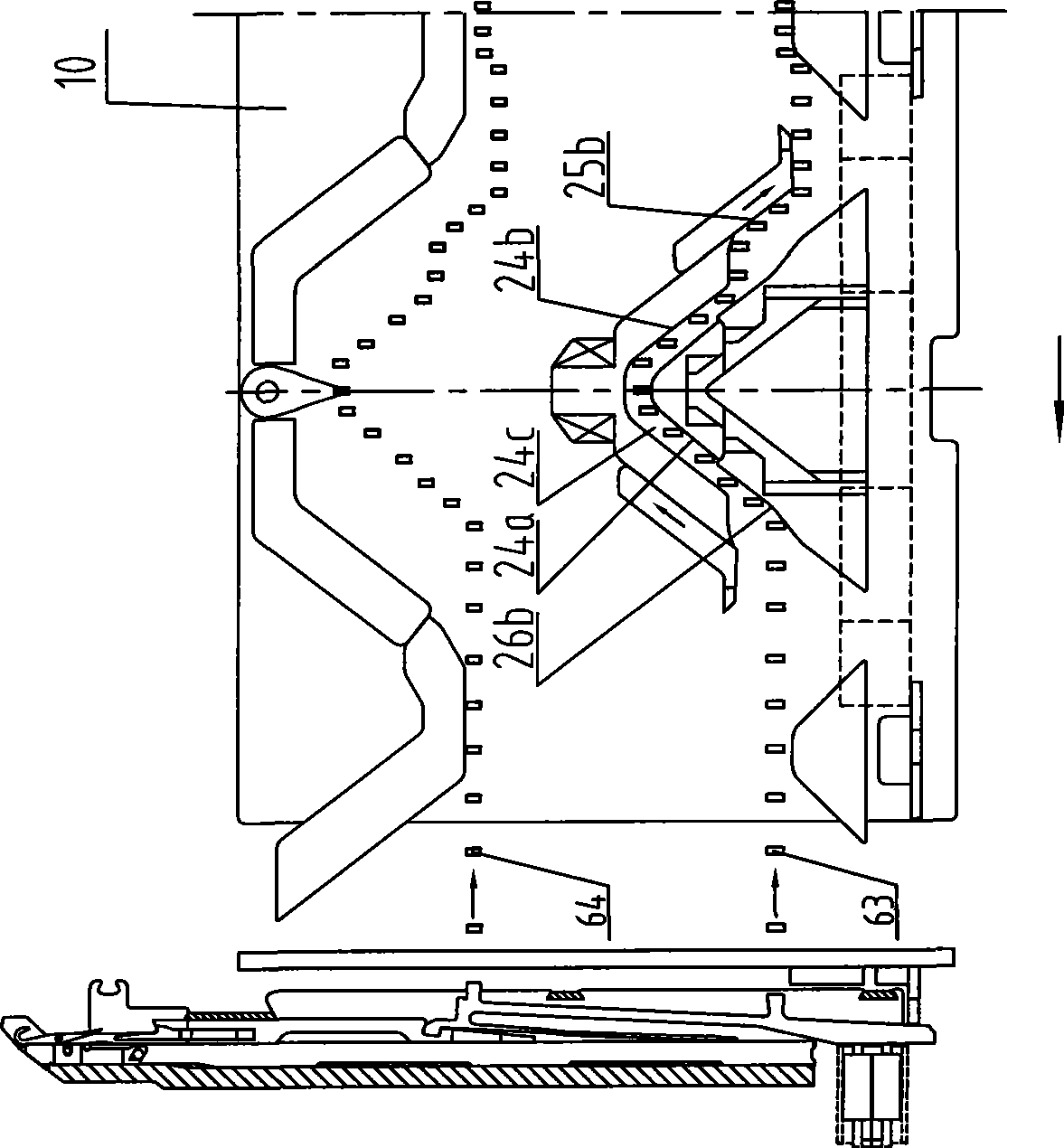
[0028] In the following embodiments, the random head of the knitting unit moves to the left, and the butts 63 and 64 of the needle jacks in each needle slot on the needle bed move to the right with respect to the cam mechanism for example.

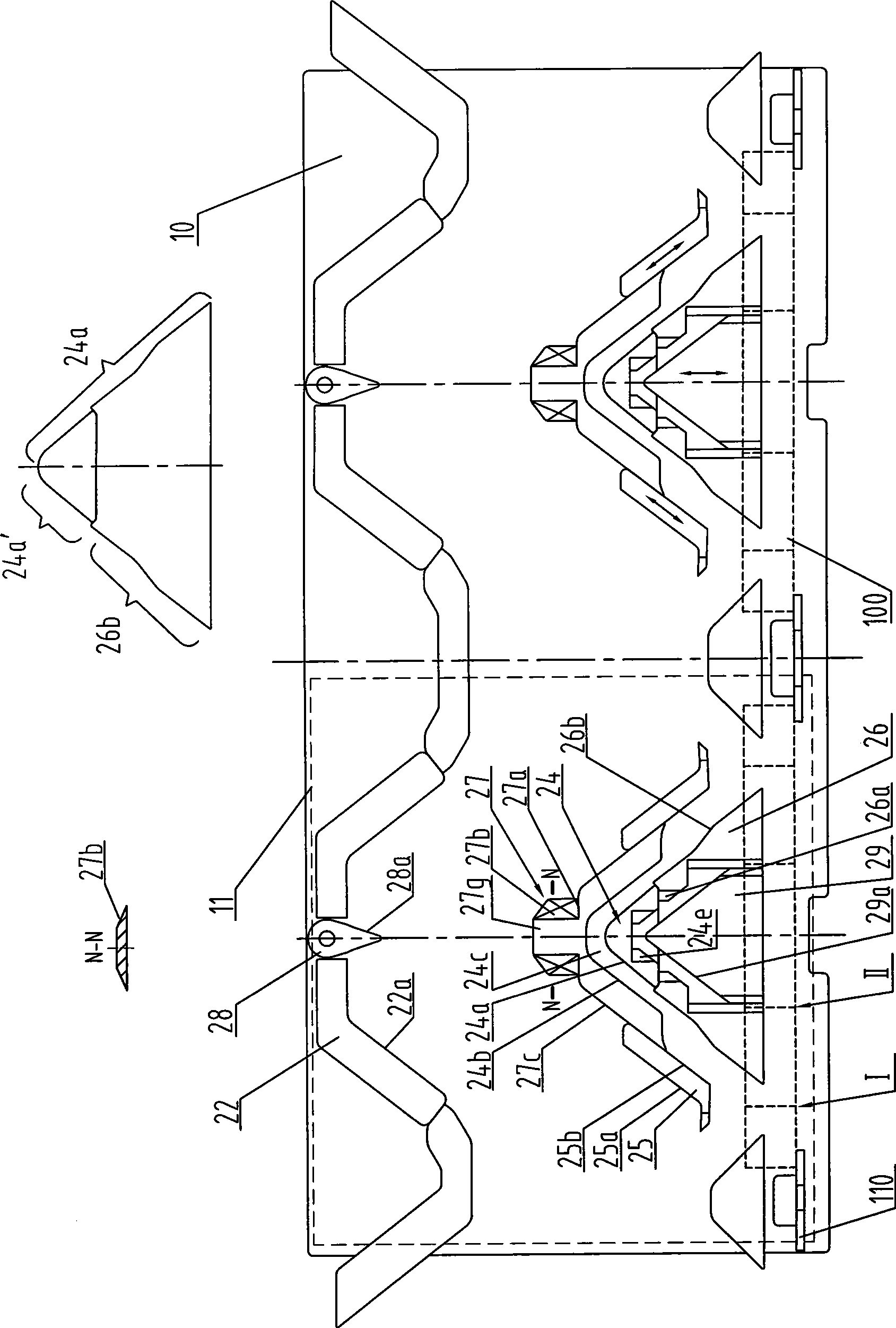
[0029] control figure 1 , The cam knitting mechanism of the present invention mainly consists of a cam bottom plate 10 and a braiding cam. Two knitting units 11 are arranged on the triangular bottom plate, and each knitting unit 11 is provided with a needle movement surface for pushing the needle clock to make the knitting needle move up and down, such as: transfer circle stop surface 22a, swing transfer circle back needle surface 28a, forming Knuckle surface 24a, needle starting surface 26b, first stitch transfer starting surface 25a, second stitch transfer starting surface 27c, stitch transfer...


PUM


Abstract

The invention relates to a triangular weaving mechanism, which is provided with a triangular base plate and at least one weaving unit; the weaving unit is provided with a plurality of needle surfaces which are positioned on corresponding weaving triangles; a loop transfer surface of each weaving unit consists of a first loop transfer running surface, a second loop transfer running surface and a loop transfer needle stabilizing surface; the first loop transfer running surface is positioned on the outside of a needle pressing surface; the second loop transfer running surface extends upward from the inside of the first loop transfer running surface to the loop transfer needle stabilizing surface; the loop transfer needle stabilizing surface is positioned at the upper end of a loop forming back stitching surface; a loop transfer back stitching surface consists of swinging loop transfer back stitching surfaces and the loop forming back stitching surface; two swinging loop transfer back stitching surfaces are attached on a swinging back stitching triangle and rotatably positioned in the center of the corresponding weaving unit; and when the two swinging loop transfer back stitching surfaces rotate to one side, a loop transfer needle track consisting of the first loop transfer running surface, the second loop transfer running surface, the loop transfer needle stabilizing surface, the swinging loop transfer back stitching surfaces and the loop forming back stitching surface is formed. The triangular weaving mechanism has the advantages of shortening stroke, improving the weaving efficiency, having short triangular base plate and low manufacturing cost, and consuming smaller materials.

Description

technical field [0001] The invention relates to a computerized flat knitting machine, in particular to a triangular knitting mechanism. Background technique [0002] When braiding thick threads, the corresponding knitting needles on the knitting machine are both larger and longer than the general knitting needles. Therefore, the pitch of the needle grooves on the needle plate is larger than the existing pitch of the needle grooves on the needle plate, so it is called thick needle pitch. At present, the triangular knitting mechanism corresponding to the thick gauge is generally enlarged according to a certain proportion according to the existing triangular knitting mechanism. [0003] The applicant of the present invention has previously proposed an invention application (application number: 200810124454.4) called a triangle knitting control system using electromagnetic needle selection. The structure of the triangle knitting mechanism is as follows: Figure 7 shown. Each k...

Claims


Application Information

Patent Timeline
Patent Type & Authority Applications(China)
IPC IPC(8): D04B15/36
Inventor 冯加林巫友群
Owner 冯加林
Why Eureka
Try Eureka