
Light-emitting-diode backlight device

一种发光二极管、背光的技术,应用在照明和加热设备、光学、光源等方向,能够解决减少寿命、特征恶化、降低色再现性等问题,达到减少温度分布变化、减少成本、减少数目的效果

Inactive Publication Date: 2009-09-16
SONY CORP
View PDF3 Cites 7 Cited by
  • Summary
  • Abstract
  • Description
  • Claims
  • Application Information

AI Technical Summary

Problems solved by technology

Specifically, in LED backlight devices, the luminous efficiency of red LEDs decreases under high-temperature environments, thereby degrading color reproducibility
The effect of higher temperature in display devices causes not only the aforementioned problems in LED backlight devices but also problems such as reduced lifespan and deterioration of characteristics of, for example, integrated circuit devices mounted to various circuit unit substrates or electronic parts

Method used


Image

  • Light-emitting-diode backlight device
  • Light-emitting-diode backlight device
  • Light-emitting-diode backlight device

Examples


Embodiment Construction

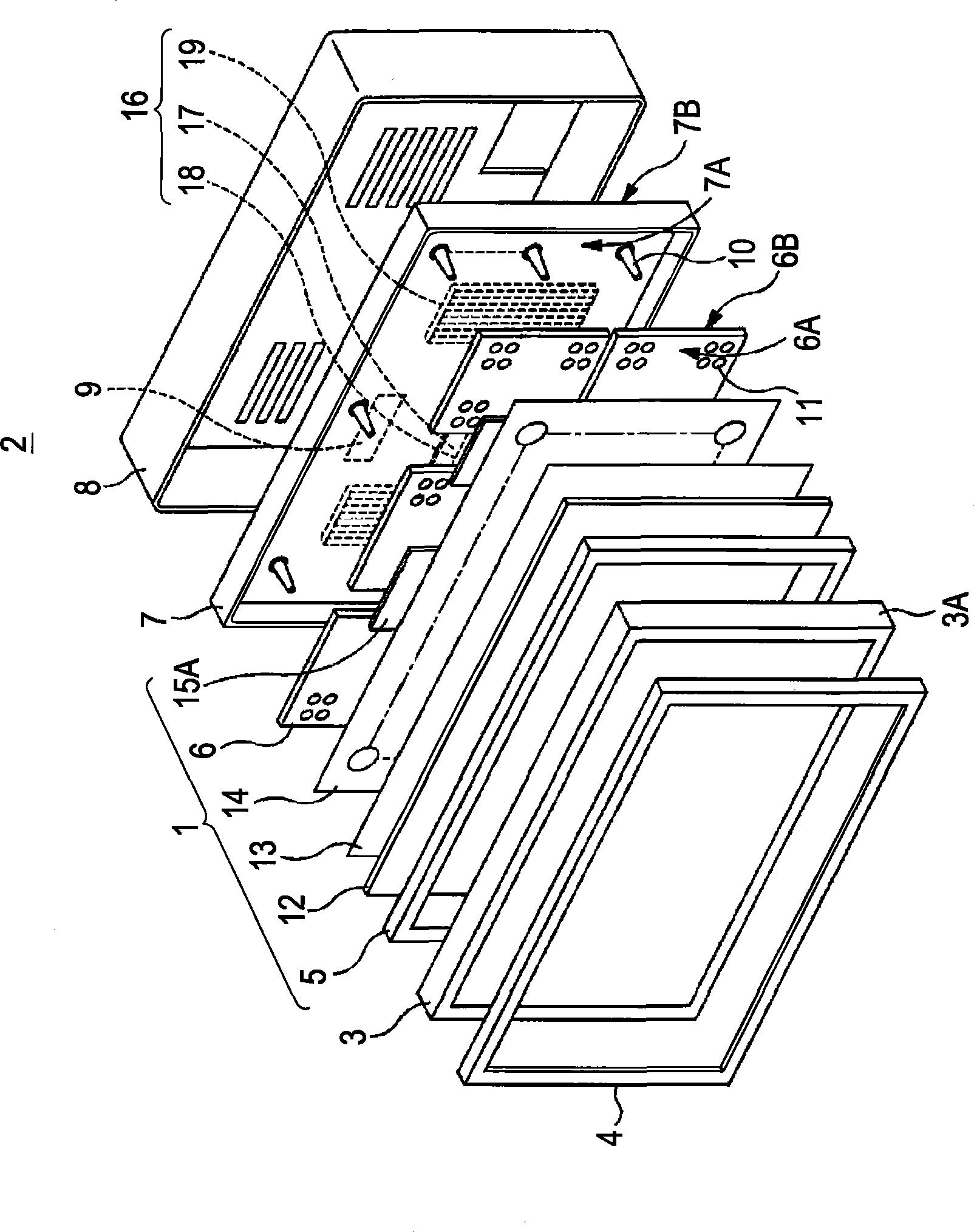
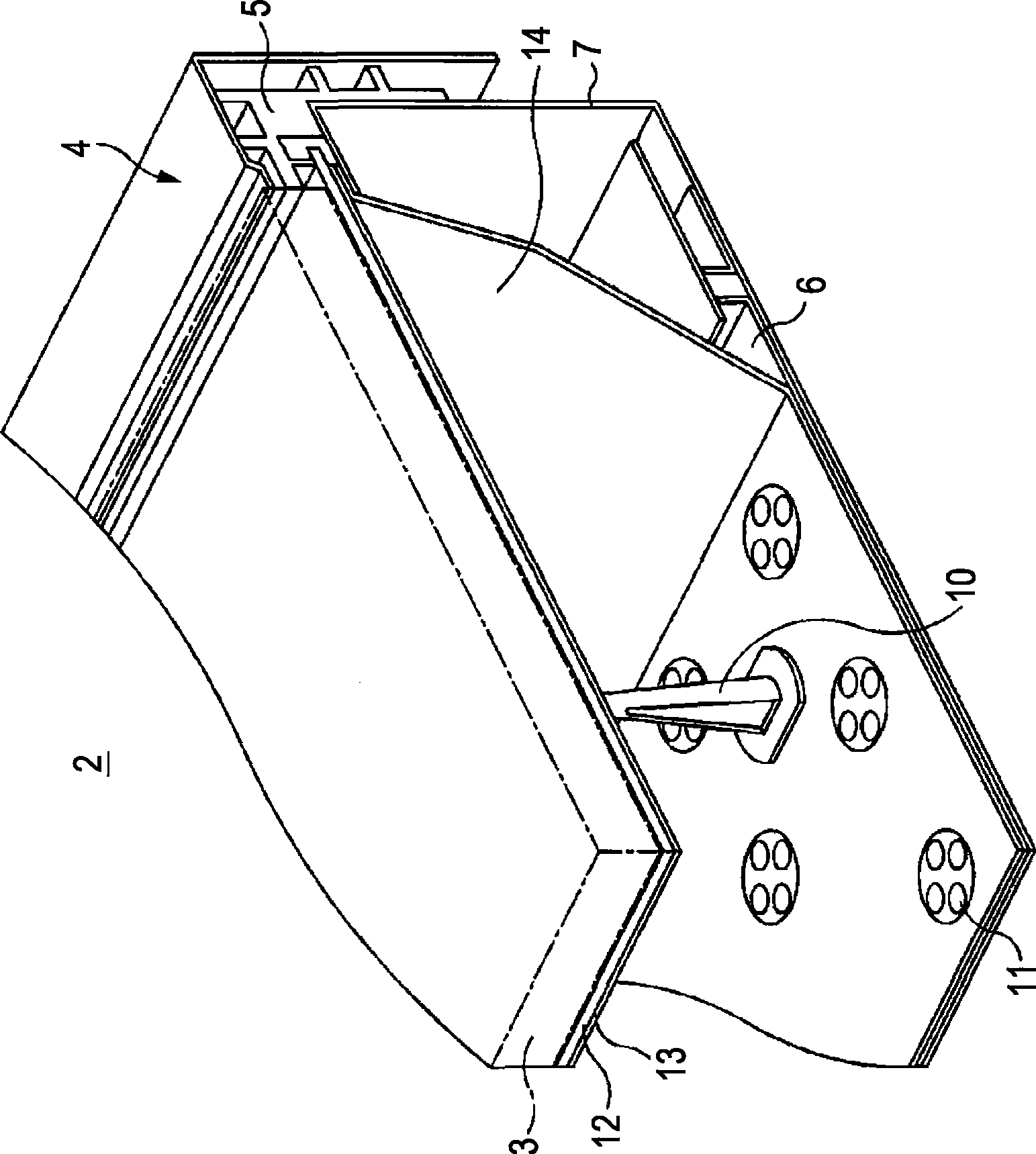
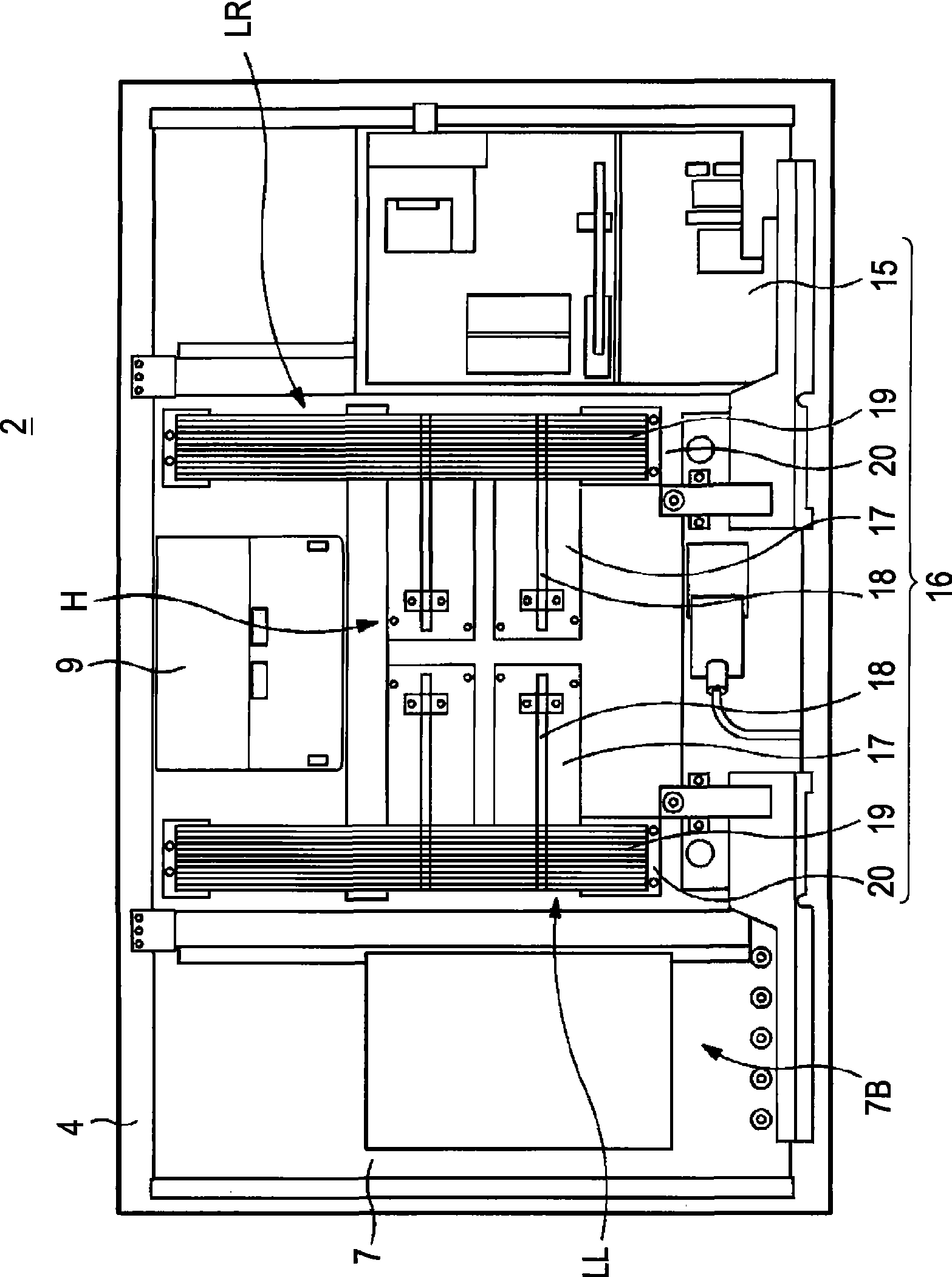
[0026] A large-scale liquid crystal color display device (hereinafter simply referred to as "liquid crystal display device") 2 including an LED backlight unit (hereinafter simply referred to as "liquid crystal display device") as an LED backlight device according to an embodiment of the present invention will be specifically described with reference to the accompanying drawings. backlight unit"). The liquid crystal display device 2 is used, for example, in a television receiver or various display monitoring devices. like figure 1 As shown in , in liquid crystal display device 2 , front chassis (frame) 4 is assembled to the front surface side of liquid crystal panel unit 3 , and backlight unit 1 (which supplies illumination light) is assembled to the back surface side of liquid crystal panel unit 3 .

[0027] In the liquid crystal display device 2 , the liquid crystal panel unit 3 and the backlight unit 1 are assembled to each other in a stacked state through the middle chassi...


PUM


Abstract

A light-emitting-diode backlight device includes a light source substrate to which many light-emitting diodes are mounted, and a bottom chassis having the light source substrate mounted to a principal surface side of the bottom chassis. Illumination light from the light-emitting diodes is supplied to a display panel unit. A back-surface side of the bottom chassis is provided with a heat-dissipating unit making uniform a temperature distribution over the entire bottom chassis. The heat-dissipating unit includes a mounting plate, a heat pipe, and a radiating fin. The mounting plate is mounted to at least a high-temperature area of the bottom chassis. The heat pipe is disposed on both the high-temperature area and a low-temperature area, and is mounted to the mounting plate. The radiating fin is mounted to the low-temperature area, and connected to an end of the heat pipe.

Description

[0001] Cross References to Related Applications [0002] The present application contains subject matter related to Japanese Patent Application JP 2008-064450 filed in the Japan Patent Office on Mar. 13, 2008, the entire content of which is hereby incorporated by reference. technical field [0003] The present invention relates to an LED backlight device in which a plurality of light emitting diodes (LEDs) are used as light sources. Background technique [0004] The LED backlight device is, for example, assembled to a display screen such as a liquid crystal display screen, and illumination light emitted from each LED is supplied to a display screen unit to form a display device. For example, compared to cold cathode fluorescent lamps (CCFLs) generally used as light sources in the related art, LED backlight devices are provided with a plurality of LEDs which are inexpensive and have various features such as small size / light weight, low electric power consumption Or the lumin...

Claims


Application Information

Patent Timeline
Patent Type & Authority Applications(China)
IPC IPC(8): F21S8/00F21V19/00F21V29/00H01L23/34G02F1/13357G02F1/133F21Y101/02
CPCG02F1/133603G02F2001/133628H01L2924/0002H05K7/2099G02F1/133628H01L2924/00G02F1/1335G02F1/1333
Inventor 柴田博一铃木雄一
Owner SONY CORP
Learn More