
Drop test device for movable impact platform

A test device and platform technology, applied in the direction of measurement device, impact test, machine/structural component test, etc., can solve problems such as affecting the real reference of the test, temperature increase, small wheel rotational inertia, etc., to avoid the wheel Elevated temperature, guaranteed authenticity, compact effect

Active Publication Date: 2009-09-16
NANJING UNIV OF AERONAUTICS & ASTRONAUTICS
View PDF0 Cites 35 Cited by
  • Summary
  • Abstract
  • Description
  • Claims
  • Application Information

AI Technical Summary

Problems solved by technology

[0004] 1. The moment of inertia of the wheel is small, and the speed will quickly drop to zero when it hits the platform. Not only can it not realistically simulate the touchdown and take-off process of the landing gear wheel, but the research on the characteristics of the landing gear is only limited to an instant rather than a continuous process;
[0005] 2. When the wheel touches the impact platform, the wheel rotates at a fixed point on the platform instead of sliding and rolling forward like when the plane lands, which inevitably adds some unreal conditions, making the simulated wheel start and return There is a certain difference between the bomb load and the real landing situation;
[0006] 3. The speed of the wheel is generated by the belt rotation of the friction wheel, which will increase the temperature of the wheel during the belt rotation process, which is inconsistent with the actual situation and will inevitably affect the test results
[0007] Therefore, when using the traditional wheel belt rotation device for the drop test, it is inevitable that these unreal conditions will be brought into the test results, which will affect the real reference of the test

Method used


Image

  • Drop test device for movable impact platform
  • Drop test device for movable impact platform
  • Drop test device for movable impact platform

Examples


Embodiment Construction

[0027] Here, the present invention will be described in further detail in conjunction with the accompanying drawings.

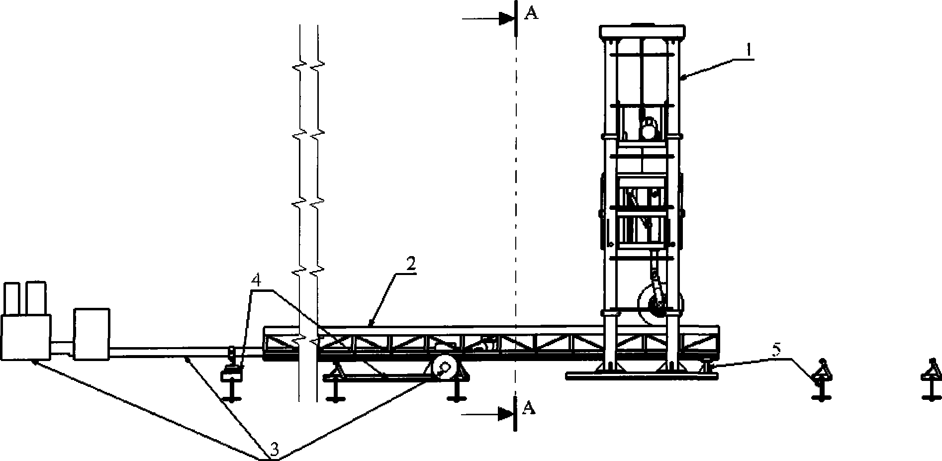
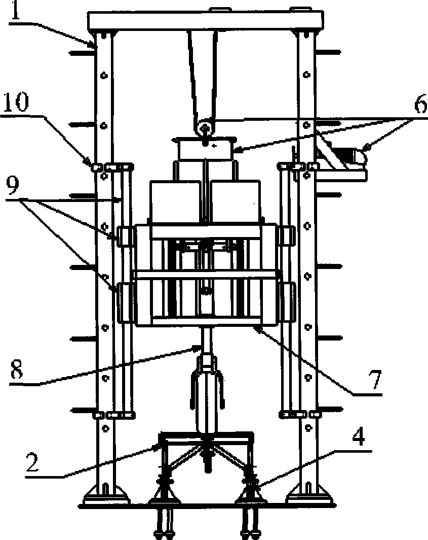
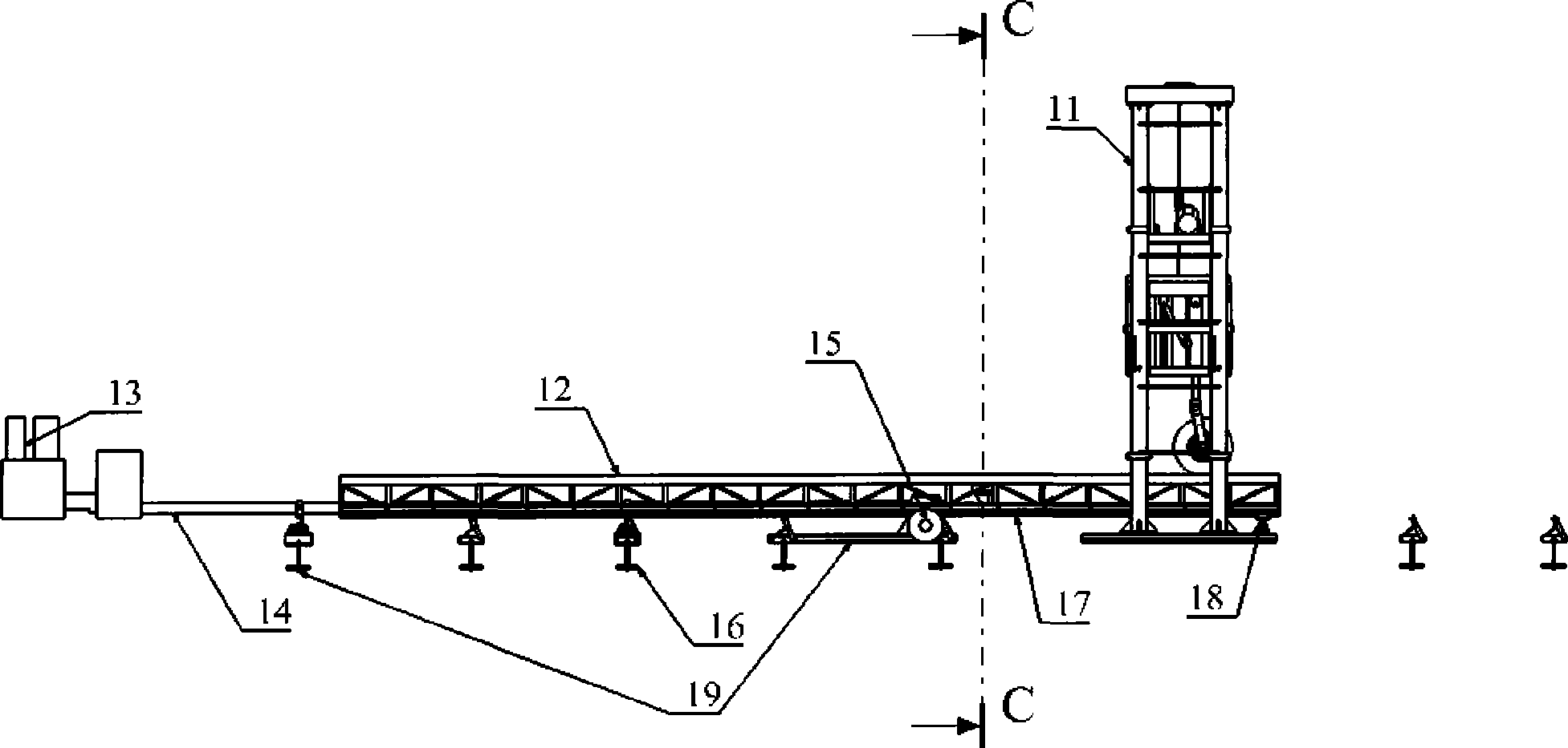
[0028] The invention provides a drop shock test device for a movable impact platform, which mainly consists of a gantry 1, a movable impact platform 2, a hydraulic drive system 3, a ground guiding mechanism 4, a ground fixing mechanism 5, a retractable mechanism 6, and a hanging basket 7 , Undercarriage 8, hanging basket guiding mechanism 9 and gap adjusting mechanism 10 are formed.

[0029] The aforementioned gantry 1 is a frame-type steel frame mechanism, which is composed of a column 11, a base plate 29, a side ladder 30 and a top beam frame 28, as image 3 , 4 shown. The column 11 is connected with the base plate 29 and the top beam frame 28 by bolts, the two columns on one side and the side ladder 30 are welded, and the gantry 1 is fixed on the ground through the ground fixing mechanism 5 .

[0030] The aforementioned movable impact platform 2 is comp...


PUM


Abstract

A drop test device for a movable impact platform can be used in the fields of spin-up drop tests of an aircraft landing gear, rolling property tests, tire static property tests and tire dynamic property tests. The drop test device for the movable impact platform comprises a portal frame, a ground fixing mechanism, a retraction jack, a hanging basket, a landing gear, a hanging basket guide mechanism, a clearance regulation mechanism, a movable impact platform, a hydraulic driving system and a ground guide mechanism. The movable impact platform of the invention consists of a truss-frame structure and high-speed guide rails, wherein the high-speed guide rails are connected with the truss-frame structure by blots through guide rail mounting holes. The hydraulic driving system is a high-speed servo proportional hydraulic system and is fixed on the ground through the ground fixing mechanism. The ground guide mechanism is two rows of guide sliding blocks which pass through the portal frame and are arranged parallelly. The movable impact platform is connected with the hydraulic driving system and is placed on the ground guide mechanism. The drop test device for the movable impact platform provided by the invention has the advantages of compact and simple structure and high strength and rigidity.

Description

technical field [0001] The invention belongs to a class of test equipment, which can be used for drop-shock start-up test, rolling characteristic test, tire static characteristic test, tire dynamic characteristic test, etc. of aircraft landing gear, so as to conduct research on landing gear cushioning system characteristics and tire characteristics. Background technique [0002] The landing gear drop test is a dynamic characteristic test that simulates the landing impact of an aircraft. With the help of the drop test, the characteristics of the landing gear system can be studied to verify whether the design parameters and structural reliability meet the design requirements, and whether it can be used for installation. [0003] The drop test bench generally adopts the wheel belt rotation device, and simulates the ground contact speed of the aircraft landing approach wheel by pre-rotating the landing gear wheel, and conducts research on the take-off and rebound characteristics...

Claims


Application Information

Patent Timeline
IPC IPC(8): G01M7/08
Inventor 顾宏斌李鹏陈大伟刘晖
Owner NANJING UNIV OF AERONAUTICS & ASTRONAUTICS
Learn More