Device for monitoring oil contamination

A monitoring device and a technology for oil pollution, which are applied in the field of systems for online monitoring of oil pollution, can solve the problems of complex equipment, high cost, cumbersome measurement methods, etc., and achieve the effect of optimizing the structure

Inactive Publication Date: 2009-09-16
XI'AN UNIVERSITY OF ARCHITECTURE AND TECHNOLOGY
View PDF0 Cites 16 Cited by
  • Summary
  • Abstract
  • Description
  • Claims
  • Application Information

AI Technical Summary

Problems solved by technology

[0004] The purpose of the present invention is to provide a kind of oil pollution monitoring device, this system can monitor the pollution degree of oil liquid o

Method used


Image

  • Device for monitoring oil contamination

Examples


Embodiment Construction

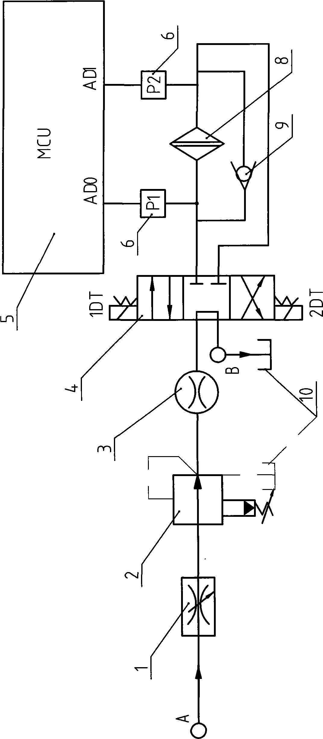
[0013] Such as figure 1 As shown, the oil pollution monitoring device of the present invention includes a speed regulating valve 1, a pressure reducing valve 2, a flow meter 3, a reversing valve 4, a microcontroller (MCU) 5, a pressure sensor 6, a filter 8, and a one-way valve 9 And oil inlet port A and oil outlet port B. In this embodiment, the reversing valve 4 is a low-pressure electromagnetic reversing valve, such as a three-position, four-way M-type electromagnetic reversing valve.

[0014] The oil inlet port A of the monitoring device of the present invention is connected with the main oil circuit of the monitored hydraulic system, and its oil outlet port B is connected with the main oil circuit oil tank 10 of the monitored hydraulic system; the speed regulating valve 1 is connected with the pressure reducing valve 2 and the flow meter 3 are connected in series along the oil inlet direction in series with the oil inlet port in the middle position of the reversing valve ...


PUM


Abstract

The invention provides a device for monitoring oil contamination. The device comprises a speed-regulating valve, a pressure-reducing valve, a reversing valve, a flowmeter, a micro controller, pressure sensors, a filter and a one-way valve, wherein the middle position of the reversing valve is provided with an oil inlet, an oil return port and two oil outlets; the device also comprises an oil inlet connected with a main oil path of a monitoring hydraulic system and an oil outlet connected with an oil tank of the main oil path of the monitoring hydraulic system; the speed-regulating valve, the pressure-reducing valve and the flowmeter which are arranged behind the oil inlet are orderly connected in series and then connected with the oil inlet at the middle position of the reversing valve; the two oil outlets at the middle position of the reversing valve are connected with an inlet and an outlet of the filter respectively; the inlet and the outlet of the filter are provided with the pressure sensors respectively; and the output ends of the pressure sensors are connected with two connectors of the micro controller respectively. The system can on-line monitor the oil contamination in the operating process of the hydraulic system.

Description

technical field [0001] The invention relates to an oil pollution monitoring device, in particular to a system for online monitoring of oil pollution in a hydraulic system. Background technique [0002] In modern hydraulic equipment, oil pollution control is very important. At present, many factories, enterprises or construction units do not carry out pollution monitoring on the oil used in hydraulic equipment, which makes the contaminated oil seriously affect the service performance and life of each hydraulic component in the system. The faults account for more than 75% of the total faults of hydraulic equipment. Therefore, it is very necessary to monitor the pollution degree of equipment oil and control oil pollution. However, the existing oil pollution monitoring methods and technologies still have the following deficiencies: most of the monitoring devices are off-line monitoring, the equipment is complex, the cost is high, the requirements for the monitoring environment...

Claims


Application Information

Patent Timeline
IPC IPC(8): G01N33/26
Inventor 贺利乐谷立臣翟小东任海军
Owner XI'AN UNIVERSITY OF ARCHITECTURE AND TECHNOLOGY
Why Eureka
Try Eureka