
Digital multifunctional special fire water supply device controller

A technology for water supply equipment and controllers, applied in electric controllers, controllers with specific characteristics, and program control in sequence/logic controllers, etc., can solve problems such as poor accuracy and reliability, single function, easy "crash" problems, to achieve the effect of improving accuracy and reliability, enriching functional modules, and improving program efficiency

Inactive Publication Date: 2009-09-16
孙青格
View PDF0 Cites 11 Cited by
  • Summary
  • Abstract
  • Description
  • Claims
  • Application Information

AI Technical Summary

Problems solved by technology

[0003] In the past, the controller of fire water supply equipment was composed of a single-chip microcomputer. The disadvantage is that the anti-interference ability is poor, and it is easy to "crash" during operation.
Moreover, because the program is often solidified in the memory and there is no simple programming device, it is inconvenient to modify the program. If you want to modify the program at the construction site, it is impossible. You can only unplug the memory and bring it back to the factory for processing, reducing ease of operation
[0004] At present, Program Logic Controller (Program Logic Control; hereinafter referred to as: PLC) is widely used as the controller of fire water supply equipment, but this technology still has defects such as single function, poor accuracy and reliability, and can only complete the process control of general actions

Method used


Image

  • Digital multifunctional special fire water supply device controller
  • Digital multifunctional special fire water supply device controller
  • Digital multifunctional special fire water supply device controller

Examples


no. 1 example

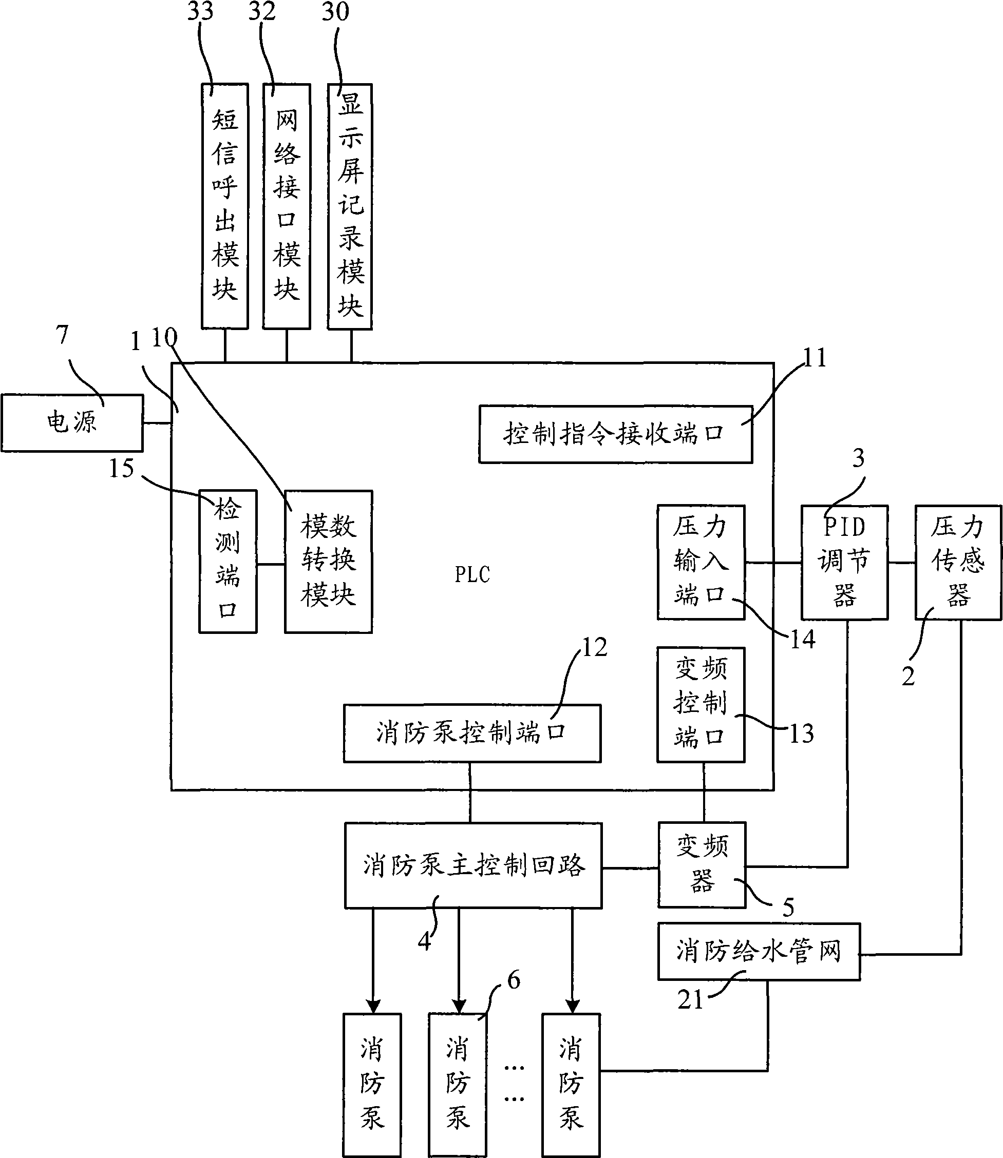
[0021] figure 1 It is a schematic diagram of the structure of the digital multi-functional dedicated fire-fighting water supply equipment controller provided by the first embodiment of the present invention. The fire-fighting water supply equipment controller is a digital controller dedicated to fire-fighting water supply equipment. The structure of the controller includes: PLC 1, pressure The sensor 2 and the PID regulator 3 also include any one or more of the analog-to-digital conversion module 10 , the display screen recording module 30 , the network interface module 32 and the short message calling module 33 .

[0022] Among them, PLC 1 is the core control component of the control system, including arithmetic units and controllers, capable of storing system programs and user programs. The PLC 1 is provided with a plurality of input ports and output ports, specifically including at least a control command receiving port 11 , a fire pump control port 12 and a frequency conve...

no. 2 example

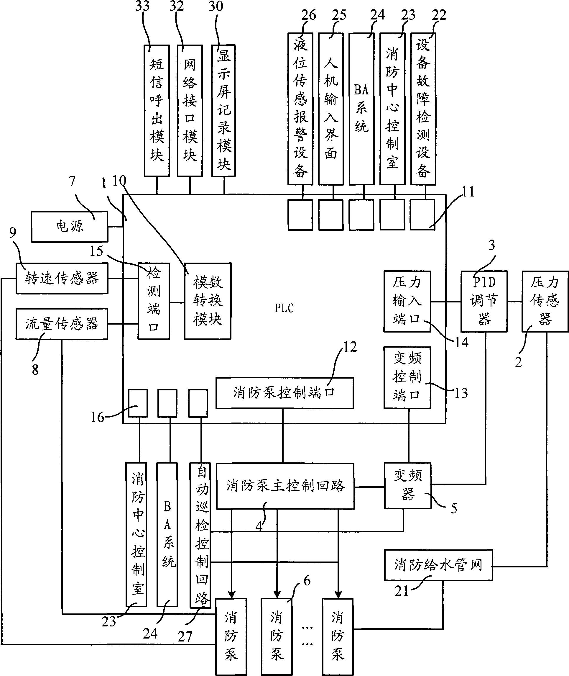
[0032] figure 2 It is a schematic diagram of the structure of the digital multifunctional dedicated fire water supply equipment controller provided by the second embodiment of the present invention. This embodiment can be based on the above-mentioned first embodiment, and further includes a flow sensor 8 and a rotational speed sensor 9 .

[0033]Wherein, the flow sensor 8 is connected to the detection port 15 of the PLC 1 for connecting to the fire pump 6 to detect the flow of the fire pump 6 , and generates a flow signal to be transmitted to the detection port 15 . The rotational speed sensor 9 is connected to the detection port 15 of the PLC 1 for connecting to the fire pump 6 to detect the rotational speed of the motor of the fire pump 6 , and generates a rotational speed signal to be transmitted to the detection port 15 .

[0034] In this embodiment, sensors are added to the digital multifunctional special fire water supply equipment controller, which can enrich the dete...

no. 3 example

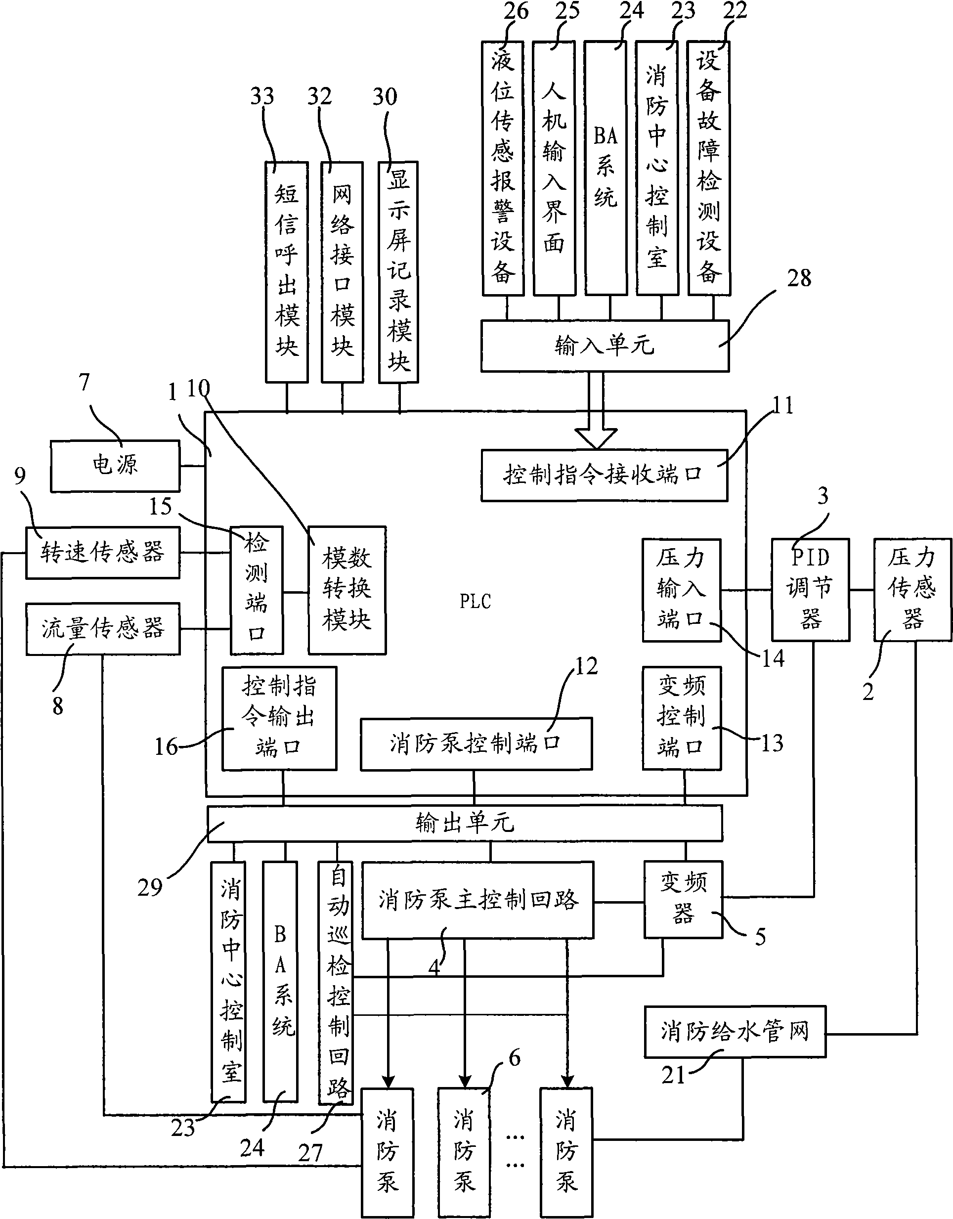
[0045] image 3 It is a schematic diagram of the structure of the digital multifunctional special fire water supply equipment controller provided by the third embodiment of the present invention. This embodiment can be based on the above-mentioned second embodiment, and an input unit 28 and an output unit 29 are further added.

[0046] The input unit 28 includes a plurality of relays, which are respectively connected between each control instruction receiving port 11 and the correspondingly connected equipment, for example, connected to the equipment fault detection equipment 22, the fire control center control room 23, the BA system 24, the man-machine input interface 25 and Between the liquid level sensing alarm device 26 and the control instruction receiving port 11 . The control commands and alarm signals issued by the above-mentioned devices all control the respective connected relays with switching values, and the output terminals of the relays are connected to the inpu...


PUM


Abstract

The invention relates to a digital multifunctional special fire water supply device controller, comprising a programmable logic controller, a pressure sensor and a PID adjustor; wherein, the programmable logic controller is provided with a steering instruction receive port, a fire pump control port and a frequency conversion control port, the steering instruction receive port is used to receive digital steering instructions, the fire pump control port is used to be connected to a fire pump main control loop to control startup and stop of the fire pump, and the frequency conversion control port is used to be connected to a frequency converter to control operation of the frequency converter; the pressure sensor is used to be connected to a fire water supply network to detect network pressure and generate simulated pressure signals; the PID adjustor is used to process the simulated pressure signals and then transmit the signals to the frequency converter to control output frequency of the frequency converter and convert simulated pressure signals into digital signals and transmit the signals to the programmable logic controller; the controller further comprises a analog-to-digital conversion module, a display screen logging module, a network interface module and / or a short text message outgoing module. The invention can realize digitalized control and improve accuracy of the control.

Description

technical field [0001] The present invention relates to the control technology of fire-fighting water supply, in particular to a digital multifunctional special-purpose fire-fighting water supply equipment controller. Background technique [0002] The fire protection system is an indispensable facility in all kinds of buildings, and the fire water supply equipment is an important part of the fire protection system. Among them, the controller plays an important role as the control center of the fire water supply equipment. The main function of the fire water supply equipment controller is to identify and process the control instructions when receiving the control instructions, control the operation of the main control circuit of the fire pump, start or stop the fire pump to supply water to the fire water supply pipe network, and at the same time, according to the control instructions Control the frequency converter, the frequency converter is connected to the main control ci...

Claims


Application Information

Patent Timeline
IPC IPC(8): G05B19/05G05B11/36
Inventor 孙青格
Owner 孙青格
Learn More