Battery

A technology for batteries and current collectors, applied to secondary batteries, battery pack parts, battery caps/end caps, etc. Effects of poor contact, suppression of increase in connection resistance, and stabilization of contact state

Inactive Publication Date: 2009-09-16
GS YUASA INT LTD
View PDF3 Cites 5 Cited by
  • Summary
  • Abstract
  • Description
  • Claims
  • Application Information

AI Technical Summary

Problems solved by technology

Therefore, there is a problem that when the lithium ion secondary battery is dropped or the like is impacted, the fastening portion 54c rotates, and the contact state between the negative electrode terminal 54 and the current collector 57 tends to deteriorate, and the connection resistance increases.
However, there is a problem that the process becomes complicated due to the addition of a welding process, and a part of the insulator 56 is melted due to the heat energy of welding, and the sealing performance of the cover portion 53 formed by the insulator 56 deteriorates, and the non-aqueous electrolyte may leak out.
[0017] In the battery disclosed in the above-mentioned Utility Application Publication No. 5-31108, the rotation of the rivet is suppressed, but when the battery is dropped or subjected to an impact, the fastening part of the rivet and the contact part of the gasket may be deformed, resulting in poor contact.
[0018] In the battery disclosed in Japanese Patent Laid-Open No. 2003-45404, protrusions are continuously provided in a circular shape around the periphery of the electrode lead-out plate. Therefore, there is a problem that when fastening the outer ends of the electrode lead-out pins to the electrode lead-out plate, It is difficult for the electrode lead-out pins to go deep into the electrode lead-out plate side. In addition, the electrode lead-out pins are easy to rotate relative to the ring-shaped protrusion. When an impact is applied to the battery, poor contact may occur.
[0019] In the battery disclosed in Publication No. 7-27051, the feet of the rivet terminals are oblong in plan view and have a long circumference. In addition, the distance from the central axis varies depending on the position of the end edges of the feet. Therefore, it is difficult to tighten them evenly. solid, there is a possibility of poor contact between the foot and the lead member
[0020] In the battery disclosed in JP-A-6-231740, similarly to the above, the process becomes complicated due to the addition of a welding process, and a part of the synthetic resin cover part may be melted due to the heat energy of the welding, and the cover part and the gasket are separated. Deterioration of contact performance, deterioration of sealing performance against non-aqueous electrolytes, etc.

Method used


Image

  • Battery
  • Battery
  • Battery

Examples


Embodiment approach 1

[0057] image 3 is a perspective view showing a lithium ion secondary battery (hereinafter referred to as a battery) 1 according to Embodiment 1, Figure 4 It is a perspective view of the state of the cover part 3 of the battery 1 seen from the back side, Figure 5 It is a partially cutaway side view showing the lid portion 3 . Figure 4 In , members connected to the recessed portion 32 described later are omitted.

[0058] A battery 1 accommodates a flat roll-shaped electrode group and a non-aqueous electrolyte (not shown) in a roughly cuboid-shaped aluminum casing 2 having an opening on one side, and covers the casing 2 with an aluminum cover 3 The flat rolled electrode group is obtained by winding a negative electrode plate formed by coating a negative electrode mixture on a copper current collector and a positive electrode plate formed by coating a positive electrode mixture on an aluminum current collector through a separator. .

[0059] One end of the cover 3 is prov...

Embodiment approach 2

[0073] The battery of the second embodiment has the same configuration as the battery 1 of the first embodiment, and the rotation suppression structure of the joint portion between the negative terminal 4 and the current collector 11 is different from that of the first embodiment.

[0074] Figure 9 It is a perspective view showing a state in which the end of the negative electrode terminal 14 is inserted into the insertion hole 11a of the current collector 11, Figure 10 It is a longitudinal sectional view showing the main part of the battery cover.

[0075] Such as Figure 9 As shown, the current collector 11 is provided with protrusions 11 b , 11 b .

[0076] When inserting the end of the leg portion 14b of the negative terminal 14 into the insertion hole 11a and fastening the end to the current collector 11, as Figure 10 As shown, the protrusions 11b, 11b, . The protrusions 11b, 11b... are formed discontinuously around the periphery of the insertion hole 11a. Therefor...

Embodiment approach 3

[0079] The battery of the third embodiment has the same configuration as the battery 1 of the first embodiment, and the joint portion between the negative terminal 4 and the current collector 12 has a rotation suppressing structure combining the rotation suppressing structures of the first and second embodiments.

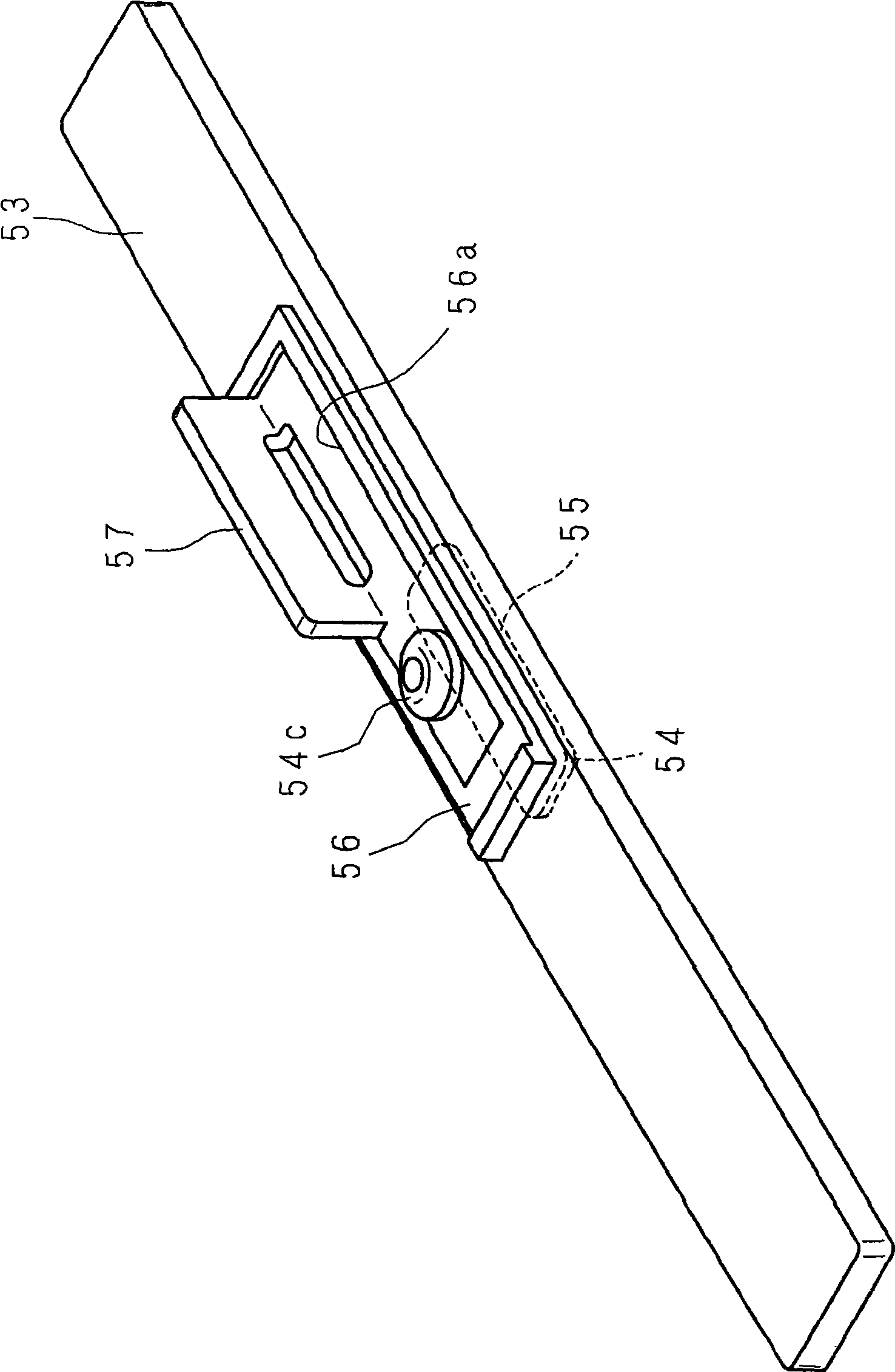
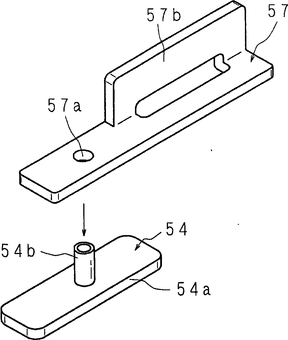
[0080] Figure 11 It is a perspective view showing a state in which the end portion of the negative electrode terminal 4 is inserted into the insertion hole 12 a of the current collector 12 .

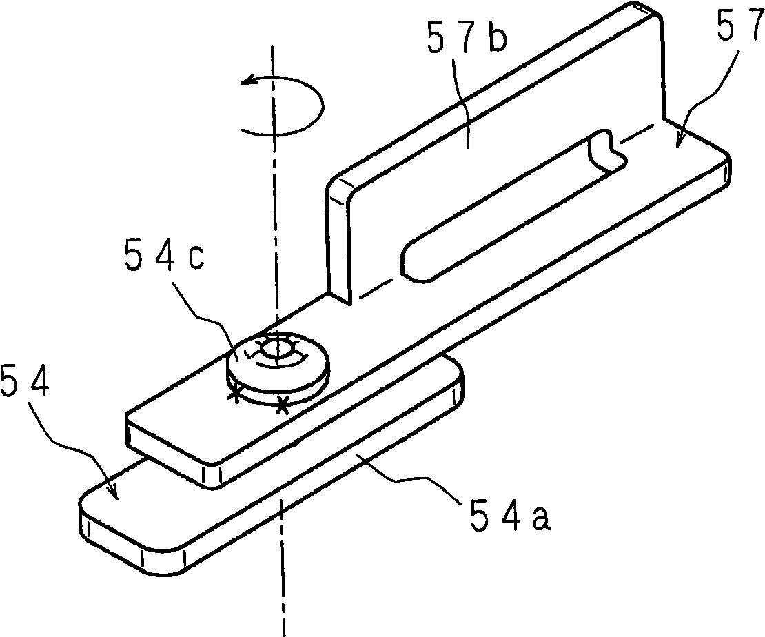
[0081] Such as Figure 11 As shown, in the insertion hole 12a of the current collector 12, similarly to the current collector 7 of Embodiment 1, substantially semicircular cutouts 12b, 12b are provided, and further, the openings facing each other with the cutouts 12b, 12b in between are provided. The semi-annular protrusions 12c, 12c are provided in the state.

[0082] Due to the above configuration, when the end of the leg portion 42 of the negative terminal 4 is inserted ...


PUM

PropertyMeasurementUnit
particle diameteraaaaaaaaaa
thicknessaaaaaaaaaa
thicknessaaaaaaaaaa

Abstract

A battery has current collectors and terminals in stable contacing status that represses the poor contact caused by applying impact such as falling, and fine quality and outer casing sealing performance. At a central portion of a lid (3) of a battery, a negative terminal (4), which has a T-shaped section view, is provided so as to be surrounded by a gasket (5) and pierce the lid (3). An insulator (6) is provided at the inner face side of the lid (3). A plate-like current collector (7) is placed in a recess (6a) of the insulator (6). Notches (72a) are provided at two positions of an insertion hole which is provided at one end portion side of the current collector (7). By inserting the negative terminal (4) into the insertion hole and crimping an end portion of a leg portion (42) of the negative terminal (4), the negative terminal (4) is fixed to the current collector (7) with a deforming part of the end portion eating into the notches (72a) and being locked.

Description

technical field [0001] The present invention relates to a battery formed by accommodating battery elements in a case and covering an opening of the case with a cover portion. Background technique [0002] In recent years, with the miniaturization, weight reduction and diversification of portable electronic devices such as video cameras, on-board computers, and mobile phones, there is a strong demand for the development of small and lightweight power supplies that have high energy density, storage stability, and high reliability. , A secondary battery that can be repeatedly charged and discharged for a long time. [0003] Secondary batteries satisfying these requirements include nonaqueous electrolyte secondary batteries containing a nonaqueous electrolyte. [0004] A lithium ion secondary battery is mentioned as a representative example of a nonaqueous electrolyte secondary battery. The lithium-ion secondary battery has a negative electrode composed of an active material c...

Claims


Application Information

Patent Timeline
Patent Type & Authority Applications(China)
IPC IPC(8): H01M2/30H01M2/06H01M2/04H01M2/26H01M10/058
CPCH01M2/30Y02E60/12H01M2/22H01M2/0426H01M10/0525Y02E60/10H01M50/169H01M50/528Y02P70/50H01M50/564H01M50/553H01M50/176H01M50/147H01M50/543
Inventor 奥田守彦团野浩之奥谷仰
Owner GS YUASA INT LTD
Why Eureka
Try Eureka