
Sand table type monitoring and commanding system

A command system, sand table technology, applied in the direction of signal transmission system, closed-circuit television system, non-electrical signal transmission system, etc., can solve the problems that public security personnel cannot directly obtain video information of monitoring points at any time, and omissions, etc., to achieve good results Crack down on illegal and criminal activities, intuitive and easy to operate, and easy to make

Inactive Publication Date: 2009-09-16
CHANGZHOU ZHILONG TECH
View PDF1 Cites 4 Cited by
  • Summary
  • Abstract
  • Description
  • Claims
  • Application Information

AI Technical Summary

Problems solved by technology

However, the police situation is ever-changing. Judging whether there is a police situation based on the pre-set situation may miss a lot of important information. At the same time, the public security personnel cannot simply and directly retrieve the video information of the monitoring point they need at any time.

Method used


Image

  • Sand table type monitoring and commanding system
  • Sand table type monitoring and commanding system
  • Sand table type monitoring and commanding system

Examples


Embodiment 1

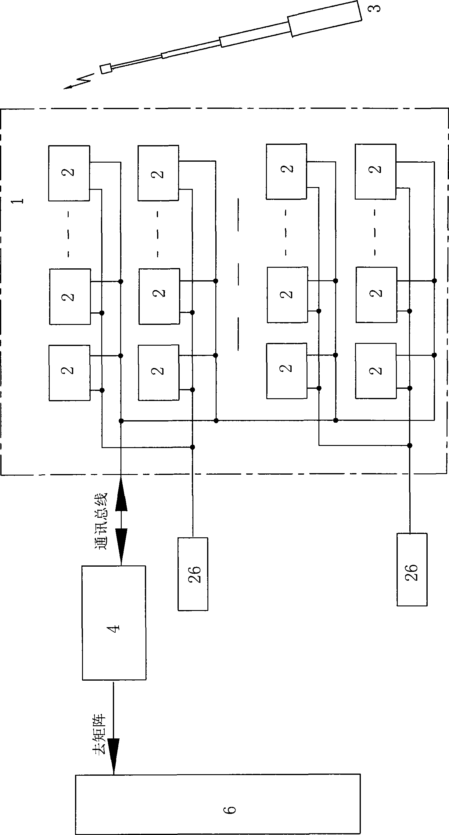
[0044] See figure 1 , a sand table-type monitoring and command system in this embodiment includes a jurisdiction map sand table 1, a plurality of indication sensing modules 2, a baton 3 and a system master controller 4. Each indicator sensing module 2 is respectively installed corresponding to the location of the actually installed camera in the jurisdiction marked on the jurisdiction map sand table 1 . All the indication sensing modules 2 are connected to form a network through the bus communication, and transmit the received wireless control signal sent by the baton 3 to the system main controller 4 through the communication bus. The system main controller 4 is connected with the matrix of the security video display system 6 through the RS232 serial interface. Security video display system 6 is the security video monitoring system usually installed in grass-roots police stations now.

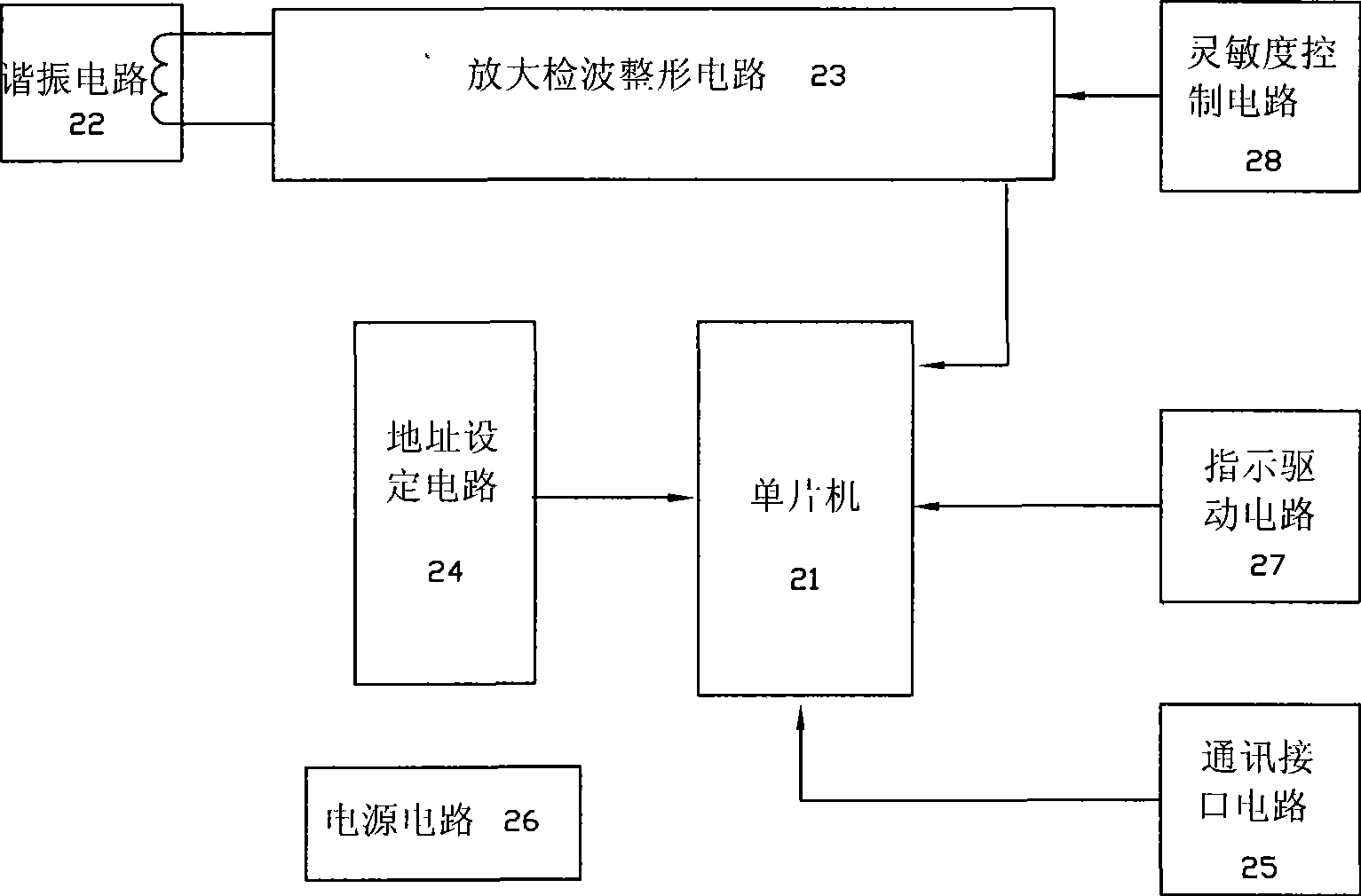
[0045] The indication sensing module 2 is mainly used to receive the trigger sensing sig...

Embodiment 2

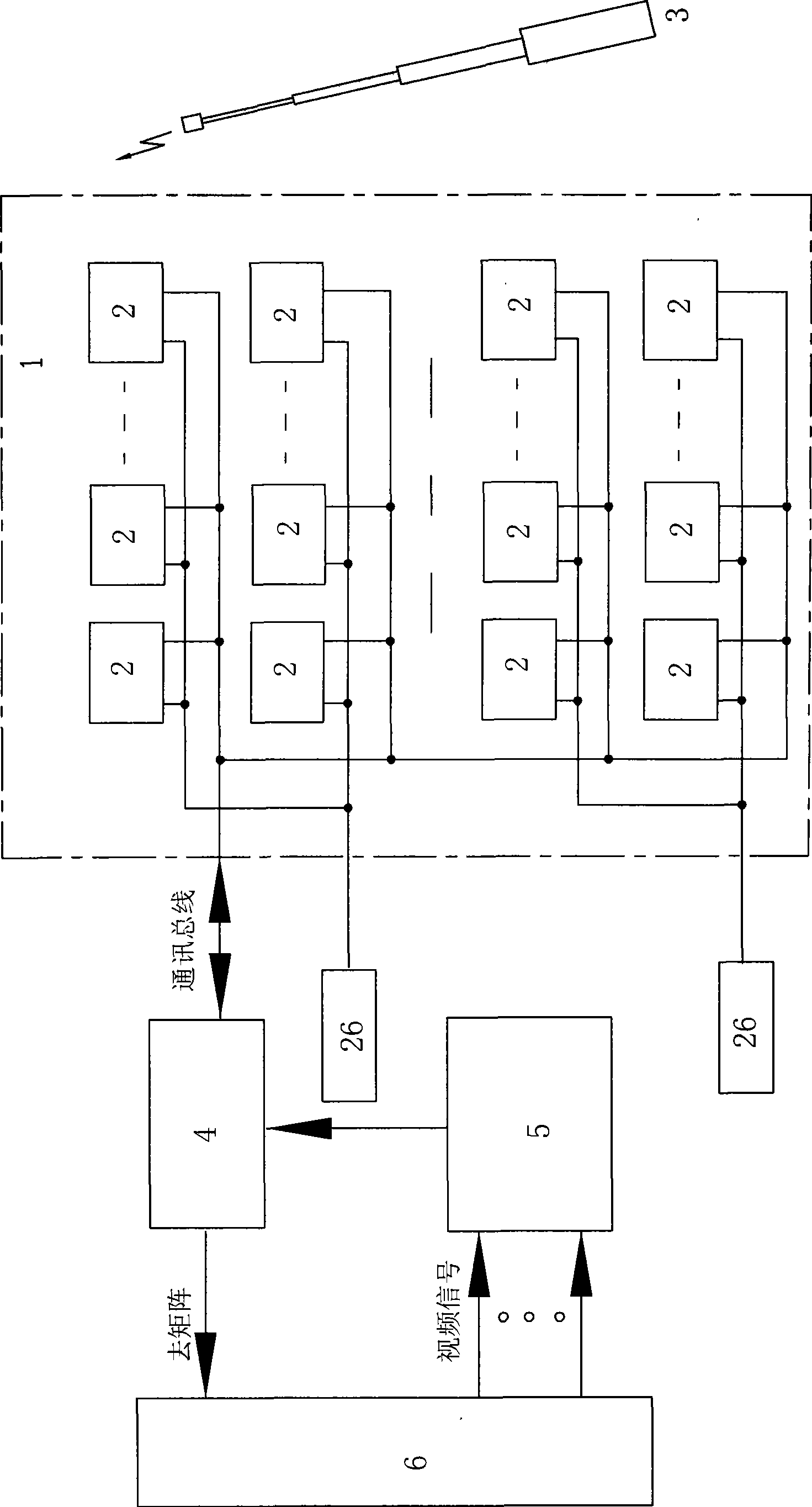
[0053] See figure 2 , the sand table monitoring command system of this embodiment is basically the same as the embodiment, the difference is that it also includes a video detector 5 connected to the system main controller 4 and a video detection circuit 48 in the system main controller 4 .

[0054] See Figure 8 with Figure 13 , video detection circuit 48 comprises video detection control output circuit 48-1, video detection data input circuit 48-2 and video detection interface circuit 48-3, the input end of video detection interface circuit 48-3 and video detection control output circuit 48- 1 is electrically connected to the output end, and its output end is electrically connected to the input end of the video detection data input circuit 48-2. The video detection control output circuit 48-1 is composed of IC13 and IC9; IC12 is the video detection data input circuit 48-2, CZ2 is the video detection interface circuit, and IC10 and encoding switches SW2 and PZ2 also serve ...


PUM


Abstract

The invention discloses a sand table type monitoring and commanding system, which comprises a sand table of a district map, a plurality of indication sensing modules, a bacon and a system master controller, wherein each indication sensing module is correspondingly arranged at the position of the district where a camera is actually arranged, and the position is marked on the sand table of the district map; and all the indication sensing modules are in communication connection via buses to form a network, and received wireless control signals sent by the bacon are transmitted to the system master controller via the communication buses. When the sand table type monitoring and commanding system is used for tracing images at the case scene of a monitoring center, a front camera image needing to be displayed is displayed on a designated monitor automatically, quickly and exactly as long as the bacon touches the indication sensing modules at corresponding positions of the sand table of the district map so as to overcome the disadvantages of complicated operation, time consumption and labor consumption of a conventional means. The sand table type monitoring and commanding system has the advantage of simple, convenient and flexible operation, so that public security officers can seize the opportunity to better overawe and crack down illegal and criminal activities.

Description

technical field [0001] The invention relates to an on-site video image tracking and display system, in particular to a sand table monitoring and commanding system composed of video signals from monitoring points. Background technique [0002] With the development of "Safe City" construction, social security monitoring systems are being built and improved in various places. In the social security monitoring system, the current common practice is to manually input the address number of the front-end camera on the control keyboard of the matrix, so that the image of the camera is displayed on the designated monitor on the monitoring wall. When switching images, it is necessary to manually repeatedly input different camera address codes. In addition, when the number of cameras in the monitoring system is relatively large, it is difficult to remember the camera number, and it is necessary to check the address number table to know, so the operation speed is slow and the time is d...

Claims


Application Information

Patent Timeline
Patent Type & Authority Applications(China)
IPC IPC(8): H04N7/18G08B13/196G08C17/02G08C23/04G09B25/00
Inventor 周玉龙詹复生舒鹏
Owner CHANGZHOU ZHILONG TECH
Learn More