Travel control device for hydraulic traveling vehicle

A driving control, hydraulic technology, applied in transmission control, components with teeth, climate sustainability, etc., can solve the problems of complex control system, increased cost of hydraulic pump, delayed response, etc., to improve overall efficiency , The effect of ensuring the driving performance and improving the acceleration feeling

Inactive Publication Date: 2009-09-16
NIHON KENKI CO LTD
View PDF2 Cites 19 Cited by
  • Summary
  • Abstract
  • Description
  • Claims
  • Application Information

AI Technical Summary

Problems solved by technology

However, since the control system is complicated as described in Patent Document 1, the capacity control of the hydraulic pump tends to cause a problem of cost increase.
In addition, when the control to increase the maximum engine speed is performed in conjunction with the capacity switching of the travel motor by self-pressure, since the control of the maximum engine speed and the travel motor are performed using the preset pu

Method used


Image

  • Travel control device for hydraulic traveling vehicle
  • Travel control device for hydraulic traveling vehicle
  • Travel control device for hydraulic traveling vehicle

Examples


Embodiment Construction

[0121] Embodiments of the present invention will be described below using the drawings.

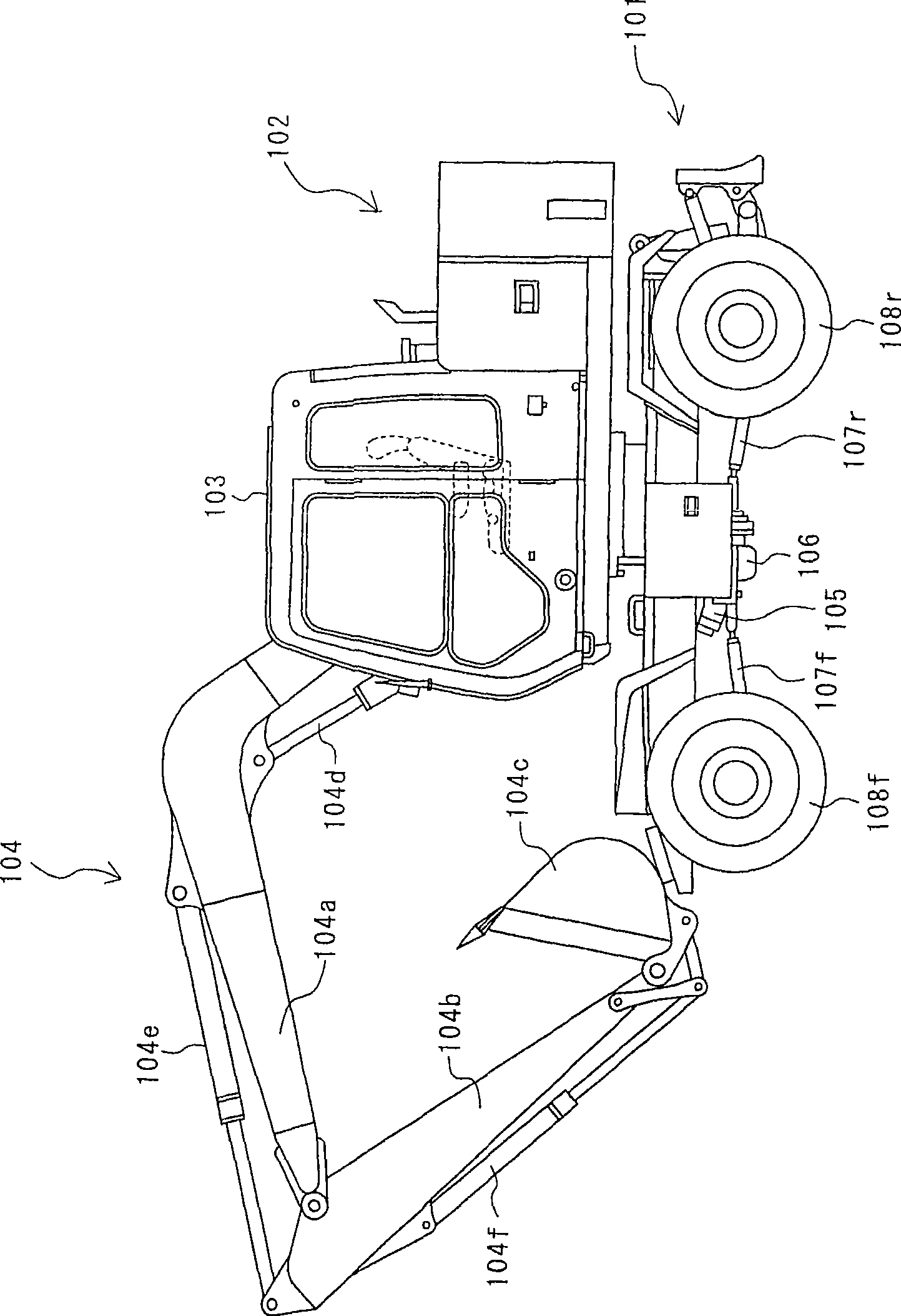
[0122] figure 1 It is a figure which shows the wheel type hydraulic excavator to which this invention is applied. This wheeled hydraulic excavator has an undercarriage 101 and an upper revolving unit 102 rotatably mounted on the upper part of the undercarriage 101 , and a cab 103 and a front attachment 104 for work are provided on the upper revolving unit 102 . . The front attachment 104 has a boom 104a rotatably connected to the main body of the upper swing body 102, an arm 104b rotatably connected to the boom 104a in the up-down and front-back directions, and The bucket 104c is connected to the arm 104b so as to be rotatable in the vertical and front-back directions. The boom 104a is driven by the boom cylinder 104d, the arm 104b is driven by the arm cylinder 104e, and the bucket 104c is driven by the bucket cylinder 104f. A hydraulic travel motor 105, a transmission 106, and propell...


PUM


Abstract

A rotational speed pickup 71 (traveling speed detection means), a hydraulic pressure sensor 72 (traveling operation detection means), a hydraulic pressure sensor 73 (drive status detection means), and a voltage sensor 74 (transmission shift position detection means) detect parameters regarding the traveling state of a hydraulic traveling vehicle. A control unit 80, a solenoid proportional valve 81, an engine control system 82, and a motor regulator 33 determine the operating state of the hydraulic traveling vehicle based on the parameters regarding the traveling state, and control the equivalent displacement of the traveling system including a hydraulic traveling motor 14 and the maximum flow rate supplied to the hydraulic traveling motor 14 according to the result of determination. The pump flow rate and motor displacement are controlled according to the traveling state in this way, thereby ensuring favorable traveling performance without degrading the fuel efficiency.

Description

technical field [0001] The present invention relates to a travel control device for a hydraulic traveling vehicle, and more particularly to a traveling control device for a hydraulic traveling vehicle such as a wheeled hydraulic excavator. A variable capacity type hydraulic travel motor driven by the supplied hydraulic oil controls the travel torque by changing the capacity of the hydraulic travel motor. Background technique [0002] The travel control device of a hydraulic traveling vehicle such as a wheeled hydraulic excavator usually uses a hydraulically driven traveling motor of variable capacity type, and the load pressure (traveling load pressure) of the traveling motor increases during acceleration, uphill travel, etc. In the case of , increase the capacity of the travel motor to generate the required torque. In addition, when decelerating, the circuit pressure (brake pressure) is adjusted through the overload relief valve in the hydraulic drive circuit for travel, a...

Claims


Application Information

Patent Timeline
IPC IPC(8): F16H61/42F16H59/40F16H59/44F16H59/68F16H61/66F16H61/4148F16H61/421F16H61/431
CPCY02T10/76
Inventor 佐竹英敏小高克明后藤勇树一村和弘近藤航
Owner NIHON KENKI CO LTD
Why Eureka
Try Eureka